Brace attachment detail, Connect brace to the stabilizer, Modify the servo control arms – Great Planes Ultra Sport 40 ARF Red - GPMA1005 User Manual
Page 19
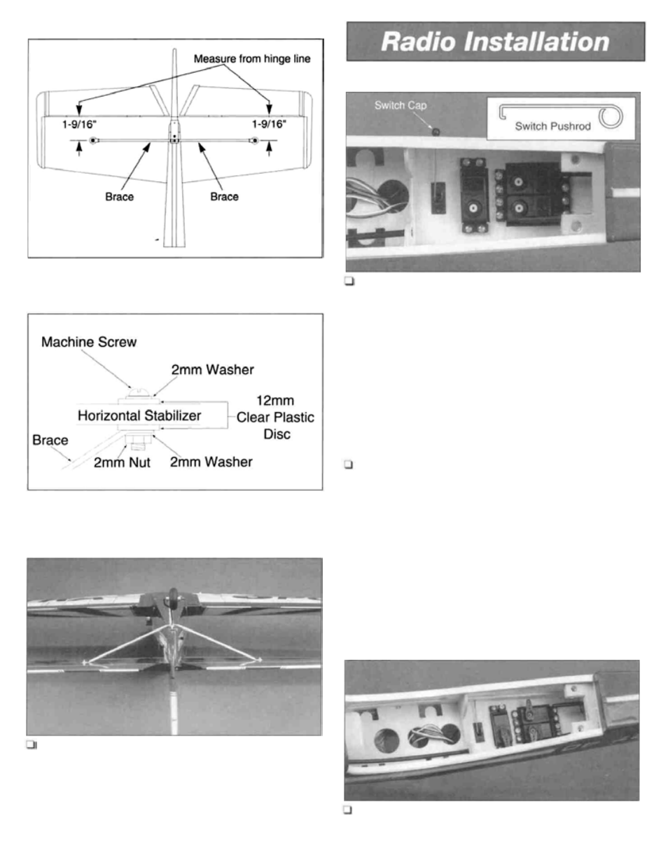
Stabilizer Brace Positioning
Mount the Switch and Servos
1. Install the switch into the precut hole in the servo
Brace Attachment Detail
tray. A piece of wire can be used to access the switch from
the exterior of the plane similar to the one illustrated in the
photograph. A piece of wire bent in the configuration of the
line illustration can also be used to access the switch from
the outside of the fuselage without the use of a switch cap.
The last part of the U-bend should be made in the wire
after the wire has been inserted into the fuselage and the
switch. A hole may need to be drilled (slightly larger than
the wire used) in the switch to allow the wire to be routed
through the switch.
as shown in the photograph above. R e f e r to the
manufacturer's manual for more detailed information.
Notice the location and orientation of each servo as well as
the switch location.
2. Install the three servos from your radio system
Connect Brace to the Stabilizer
2. Drill a 5/64" hole through the horizontal stabilizer at
the point where the brace touches the stabilizer. Insert the
2x15mm machine screw from the top side of the stabilizer
through the 2mm washer, 12mm clear plastic disc,
horizontal stabilizer, 12mm clear disc, 2mm washer, brace
and 2mm nut in that sequence. The nut should be secured
using thread locking compound.
Modify the Servo Control Arms
3. Cut three of the arms off the "cross" servo horn and
mount to the servos as shown.
19