Great Planes Sportster Bipe 40 Kit - GPMA0510 User Manual
Page 28
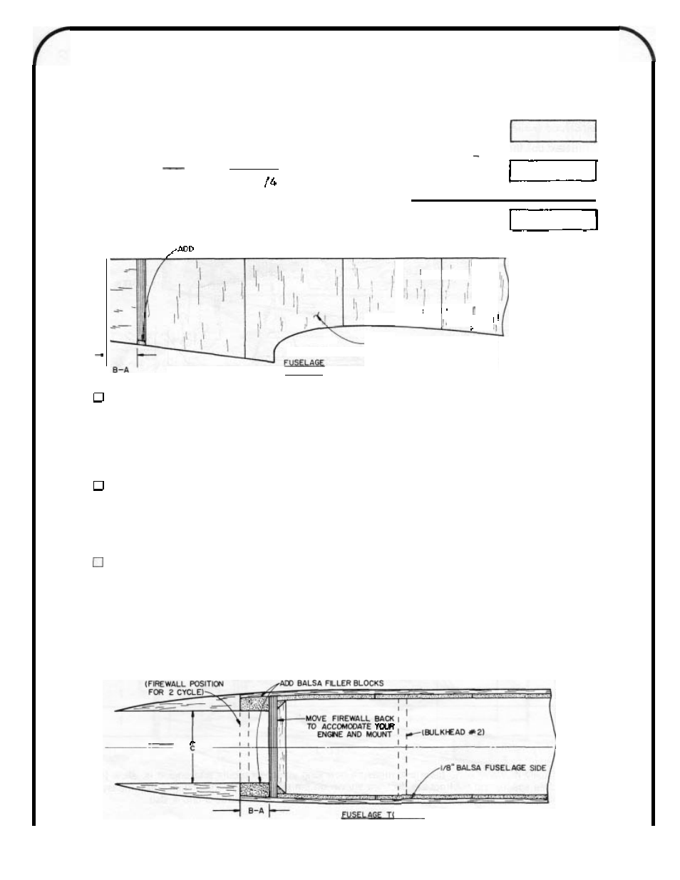
Let’s do an example to show this. Refer to the drawing showing the OS FS-61 in the Bipe. We are going
to
use a Goldberg Spinner. Our “B” measurement is 5-1/8 (measure from the front of the thrust washer to the
rear of the mount. By looking at the information in Chart 1, we know that we have to subtract 3-7/8 (Distance A)
from our distance B. The result is 1 - 1 / 4 . We move the firewall back 1 - 1 / 4 .
Example
:
B
5- 1/8
Work Area:
Your
B
-
A
-
3-7/8
1-1
?
Your A
3.
Move Firewall
Back
HARD SCRAP BALSA TO BOTTOM OF FIREWALL TO FILL ANY GAP
I’
1/8“
BALSA DOUBLER
(VERTICAL GRAIN)
SIDE VI
EW
Figure
3
MARK NEW FIREWALL
POSITION;
GLUE ON DOUBLERS
Mark the new position of the firewall on the inside
of
each Fuselage side. Make sure vour line is perfectly
parallel to the front of the fuse sides. Using the firewall as a spacer, install the 1 / 8 balsa doublers crossgrain on
the inside of the fuse side. Custom cut these pieces to fit. Do not glue the firewall in at this time. Use epoxy glue
or thick CA to glue the doublers in place. The doubler should extend past Bulkhead #3. Carefully trim the doublers
to
the fuse side shape.
11.
GLUE FIREWALL IN CORRECTED POSITION
Draw the corrected bulkhead #1 position on the top view of the plans. Next still working over the plans,
glue bulkhead #1
,
the firewall, in place. Then add 3 / 8 (or 1 / 4 depending on your mount width-see Figures 4 and
5) scrap balsa filler blocks, vertically grained, forward of bulkhead#1. Sand the blocks flush with the fuse sides.
Add 1 / 4 balsa filler below the firewall later when you remove the fuselage from the building board.
37.
GLUE
ON
THE BALSA NOSE SIDE PIECES
Check for adequate width clearance for your engine. If your 4-cycle and mount is over 2-1/4 wide, you’ll
need to cut away part of the 1 / 2 nose side pieces and 3 / 8 scrap filler pieces in the engine mount area. Or you
can custom make 3 / 8 balsa sides and 1/8 filler pieces as shown in Figure 5. Now follow step 37 in the front of
this book and glue in the side pieces.
Next,
if
desired, add a front bulkhead as shown on the full sized drawings. Make this bulkhead from
1 / 8
plywood. Once the front bulkhead is epoxied in, drill the front of this bulkhead mount for 4-40 bolts. Then tap
the mount and install 4-40 bolts.
I
\
I
\
Figure
4
FUSFl AGF TOP VlFW
28