Great Planes Sportster Bipe 40 Kit - GPMA0510 User Manual
Page 18
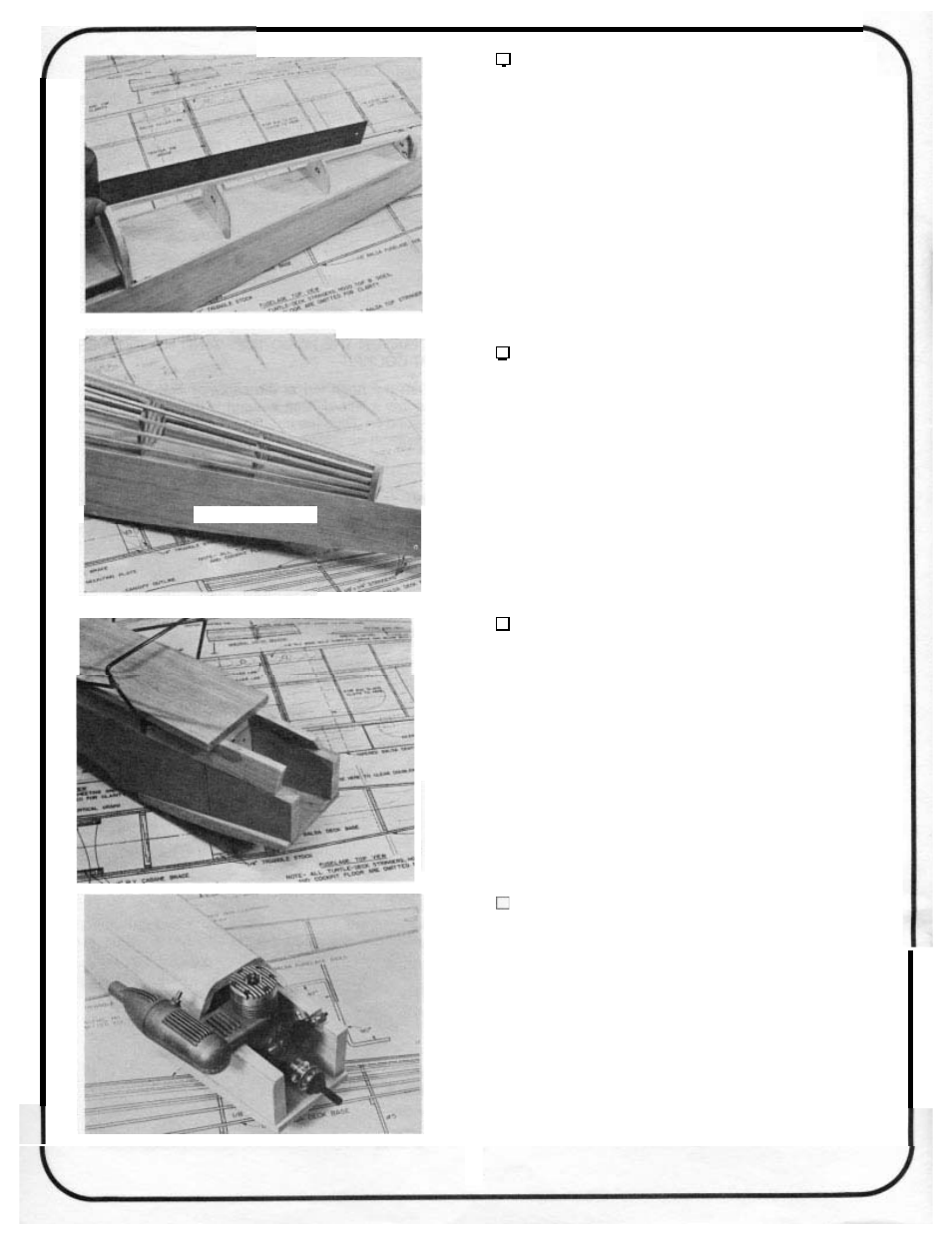
35.
ADD FORMERS 4A AND 5A
Locate the positions of formers 4A and 5A by placing
a straight edge alongthe top stringer. Placeand gluethe formers
so
they mate with the top stringer and and are centered from
side to side.
36.
ADD THE TURTLE DECK STRINGERS
Use the 1/8 x 1/4
x
16 balsa stock and cut stringers
to fit. Start by gluing at 6A/6B first, checking with a straight
edge first, and then gluing to 5A, 4A and 3A/3B.
37.
PREPARE AND GLUE IN THE SIDE NOSE
BLOCKS; FINAL SAND THE FUSELAGE FRONT
Groove the inside of the nose side block (right or left
depending on your engine) for the throttle linkage clearance.
Using 5 minute, glue the nose side blocks in place. Remove
excess epoxy at the chin block joint. Carve and rough sand the
hood top, hood sides and chin block
to
the shape of the nose
side pieces. The next few photos will help you to see the shape
needed. Don’t take
too
much off until you mount the engine
next to see where you need clearance.
38.
TEMPORARILY MOUNT THE ENGINE TO THE
Temporarily install your mount with the 4-40 bolts
provided. Place the engine on the mount. Cut away areas of
the engine compartment so the engine rests flat on the mount.
Check for binding of the throttle arm. Mark and drill the holes
in the mount for engine mount bolts. Tap the holes for bolts and
nuts or use self-tapping bolts to hold the engine on the mount.
The engine has no down thrust or right thrust.
18