Mount the motor & gearbox – Great Planes Reflection FlatOuts EP ARF - GPMA1116 User Manual
Page 15
❏
12. Slide a 1 x 149mm [3/64" x 5-7/8"] aileron link
pushrod into the clevises on each set of aileron link horns.
Adjust the clevises until each set of ailerons are parallel.
When you have the alignment correct, secure the pushrods
with a drop of glue where the pushrod enters the clevis.
Keep glue away from the end of the clevis where it pivots in
the horn.
❏
13. Slide two pushrod supports onto the elevator
pushrod 1 x 320mm [3/64" x 12-9/16"] and slide the
pushrod through the clevises on the elevator servo arm and
control horn. Adjust the clevises until the elevator is
centered with the servo centered. Secure the clevises with a
drop of glue on each clevis where the pushrod enters it.
❏
14. Using the pushrod as a guide, drill two evenly-spaced
2.4mm [3/32"] holes through the fuselage for the pushrod
guides. Glue the base of each pushrod guide into the holes.
❏
15. Install the 1 x 380mm [3/64" x 15"] rudder pushrod
the same way.
❏
16. Drill two 1.5mm [1/16"] holes through the fuselage where
shown. “Stitch” the receiver antenna through these holes.
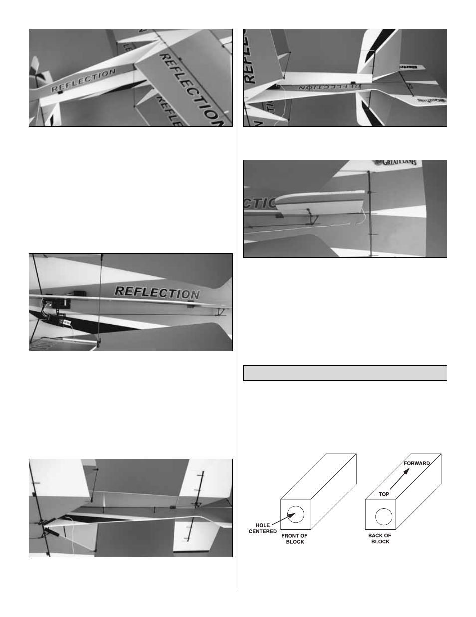
If mounting the included stick-mounted motor and gearbox
or an aftermarket geared brushless system, then follow the
instructions in this section. If mounting a firewall-mounted
motor system, proceed to “
Firewall-Mounted Motor
System” on page 17.
❏
1. The 10 x 10 x 27mm [13/32" x 13/32" x 1-1/16"]
hardwood motor mount block must be mounted in the
correct orientation. Identify the top, aft end of the block as
shown in the sketch so you will know how it is to be installed.
Mount the Motor & Gearbox
15