Great Planes Reflection FlatOuts EP ARF - GPMA1116 User Manual
Page 11
ailerons. The control horns should protrude from the bottom
of the ailerons (red and white side), and the offset Z-bend
clevises should be on the outboard sides of the horns. Glue
a control surface brace (E1) onto the roots of these two
ailerons. Remove the tube once the CA has hardened.
These will be the bottom ailerons.
❏
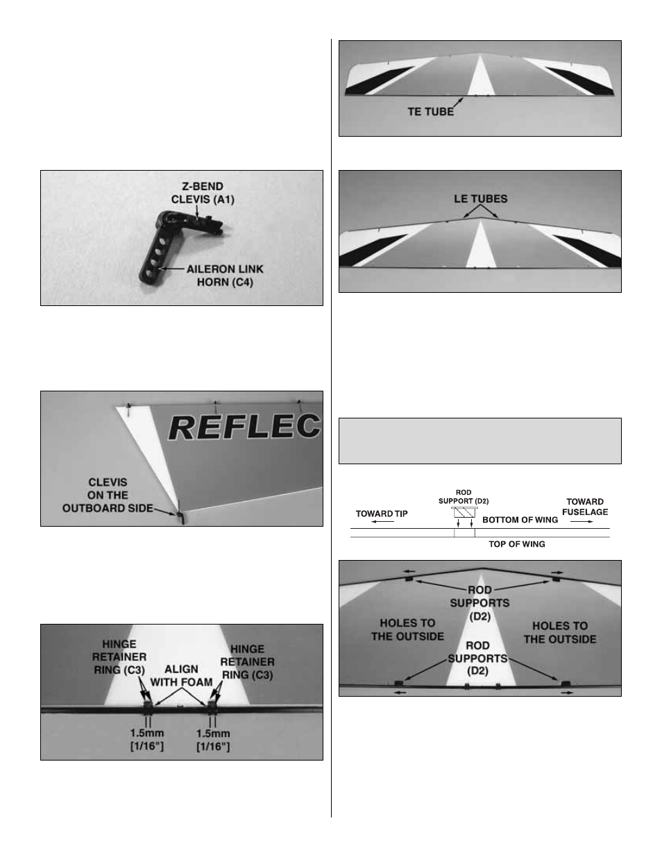
5. Install a Z-bend clevis (A1) into each of the four aileron
link horns (C4).
❏
6. Glue the aileron link horns into the slots in the TEs of
the ailerons. The Z-bend clevises (A2) should be on the
outboard side of the ailerons.
❏
7. Slide four hinge retainer rings (C3) onto each of the
wing trailing edge tubes. Position the rings so that they align
with the inner slots in the TE of the wings. Secure each
retainer with a drop of glue on the outside of the gap.
❏
8. Glue the trailing edge tubes to the TEs of the wings.
❏
9. Glue the 3 x 328mm [1/8" x 12-15/16"] wing leading
edge tubes to the LEs of the wings.
❏
10. Locate twelve rod supports (D2). In the following
steps note six of the supports will be used for the main
landing gear and six of the supports will be used for the wing
struts at the trailing edge of the wing, but all of the supports
are exactly the same.
❏
11. Installing them down through the top of the top wing,
glue four supports into the slots in both sides of the top wing.
Two of the supports are at the leading edge (for the landing
gear) and two are at the trailing edge (for the wing struts).
IMPORTANT: The holes in the supports must be angled
upward and outward (matching the angle of the landing
gear and the wing struts). This means that when viewed
from the top, the holes in each of the supports will be toward
the tips of the wing.
IMPORTANT!!! Before gluing in any of the supports, be
certain to read the steps all the way through so you will
understand how the supports go in.
11