Install the radio & ignition equipment – Great Planes Matt Chapman Eagle 580 ARF 1/3 Scale - GPMA1286 User Manual
Page 19
19
o o
3 . Position the exhaust header over the right cylinder’s
exhaust port and mark the pipe about 1-1/4" [32mm] forward
of the firewall face . Use a felt tip pen to label this as the right
hand pipe .
o o
4 . Cut the pipe to length .
o o
5 . Fit the header to the canister using a coupler and
two spring clamps . Bolt the header to the cylinder using the
hardware and any gasket that came with your engine .
o o
6 . Repeat steps 3 through 5 for the other cylinder .
o
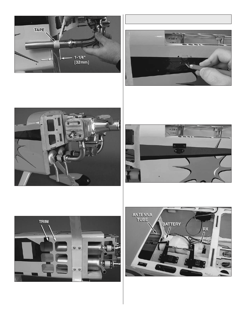
7 . Trim the covering over the six cooling ports . Note: This
is not an optional step . Muffler canisters require a generous
amount of cooling air flowing over them to prevent damage
to the surrounding structure .
Install the Radio & Ignition Equipment
o
1 . Four total positions are provided for you to mount your
radio and ignition switches . Please trim the covering from the
switch plates that suit your application . Note: To minimize the
potential for radio interference, all engine ignition equipment
(battery and switch included) must be kept at least 10"
[254mm] from all radio equipment and servos .
o
2 . Install the switches and charge jacks . Depending on
the switch and charge jack you choose, you may have to
enlarge the openings in the fuse .
o
3 . Wrap your radio battery in 1/4" [6 .4mm] latex foam
rubber and install it to the radio equipment tray . Install your
radio equipment, hookup your servos, and install any other
radio devices (servo synchronizer, servo reverser, etc .) .
Route your receiver antenna through the tube provided .