Great Planes Escapade EP/GP ARF - GPMA1200 User Manual
Page 8
8
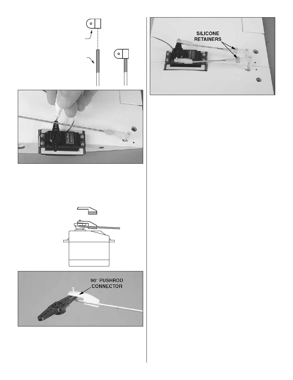
TORQUE ROD HORN
AILERON TORQUE ROD
❏
5. Screw a torque rod horn onto the right aileron torque
rod so that the top of the horn is even with the top of the
torque rod. Temporarily fi t the clevis on the end of one of the
shorter pushrod wires for the ailerons onto the horn. Use
a fi ne-point felt-tip pen to mark the pushrod wire where it
crosses the outer hole in the servo arm.
90° PUSHROD
CONNECTOR
❏
6. Disconnect the pushrod from the torque rod horn and
make a sharp, 90° bend in the wire at the mark. Enlarge the
holes in the aileron servo arm with a #48 (.076" [1.9mm]) drill
or a hobby knife. Fit the pushrod into the outer hole in the servo
arm, then attach a 90° pushrod connector to the assembly.
Cut the excess wire 1/16" [2mm] above the connector.
❏
7. Temporarily join the wings with the aluminum wing
joiner tube. Connect the other aileron pushrod the same way
you did the fi rst one. Install the servo arm screw and slip the
silicone retainers over the pushrod.
❏
8. When it’s time to join the wings for fl ying, mount the
strap to the wings as shown in step 12 on page 11. When
you want to separate the wing halves, simply disconnect the
clevis on the left aileron pushrod from the torque rod horn,
and then slide the wings apart.
Later, during fi nal radio and control throws set up, the
pushrods will be adjusted so the ailerons are centered when
the radio is on (or, you could reconnect your aileron servo to
the radio and do this now).
Proceed to Assemble the Fuselage.
8