Start-up procedure, Outdoor sensor – FloAire FAV User Manual
Page 15
15
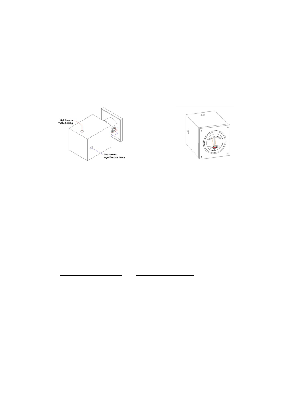
Static Pressure Controller Installation Instructions
Avoid locating the front of the static pressure controller in sun light or other areas with high ambient light
or corrosive levels. Bright light shining on the photocells can cause false actuation of the load relays.
The static pressure controller should be zeroed out before attaching the low and high pressure hoses.
The zero adjustment is located between the minimum and maximum dials.
Using the supplied rubber tubing the high side of the static pressure controller should be plumbed to the
inside of the building. The low side of the static pressure controller should be plumbed to an outdoor
sensor.
Outdoor Sensor
Use the installation instructions shipped with the outdoor sensor.
START-UP PROCEDURE
Check for signs of damage. Do not operate if damage exists and contact your manufactures sales
representative. Units are easier to fix before the equipment is installed.
Check all installation clearances.
Clearance from Combustibles
Clearance for Serviceability
Top: 6” Sides: 6” Base: 0”
Unit: 24” Service Accesses: 48”
Check that the unit has been set level and secured.
Unit must have adequate structural support or the equipment or building may be damaged.
Curb and unit must be leveled or the unit may leak or be damaged.
Gasket and caulk the seam between the curb and unit base
Screw or weld the unit’s base to the curb
to avoid damage to the equipment.
Check that the accessories are set level and secured.
Accessories must have adequate structural support or the equipment or building may be damaged
Gasket, caulk, and screw each accessory to unit seam
Check that the unit’s intake and discharge are free of debris
Check that the filter are installed in the (optional) filter section or intake hood in accordance to the air
flow direction
Check that the unit’s ductwork size and length match the minimum ductwork size chart
Check that all field wiring has been completed in accordance to the factory supplied wiring diagram
Field wires are shown as dashed lines on the wiring prints