Appendix 3: modbus rtu data structure, Rtu d, Ppendix – Flintec FT-16D V.1.21 User Manual
Page 28: Odbus, Tructure
A
PPENDIX
3: M
ODBUS
RTU D
ATA
S
TRUCTURE
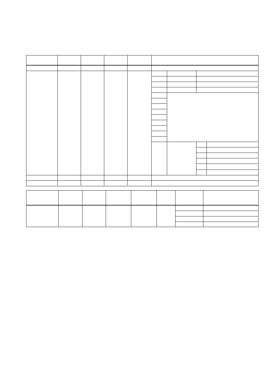
If the instrument is programmed for Modbus, it can be used as a Modbus RTU slave on a RS485
communication line or on the Ethernet communication line. The Modbus slave adress is defined in the
parameter [Address]. Function code “0x03” and function code “0x10” are supported.
Read
command
Modbus
register
Function
code
Register
address
No. of
registers
Definition
Display value
40 001
03
00,00
00,02
Current display value; Gross or Net
Bit0
Busy
1 – System Busy
Bit1
Data ok
1 – Data ok // 0 – Error
Bit2
Motion
1 – Weight is not stable
Bit3
Net Mode
1 – Net mode
Bit4
Bit5
Bit6
Bit7
Bit8
Bit9
N/A
Bit10
Bit11
Bit12
0 No
Errors
1
ADC out of range
2 ADC
overrange
3 ADC
underrange
4 System
fault
Status 40
003 03 00,02 00,01
Bit13
Bit14
Bit15
Transfer
binary (Bit13
to Bit15) to
decimal and
compare to
error code
5
FT not in weighing mode
Tare weight
40 004
03
00,03
00,02
Current tare weight
Gross Weight
40 006
03
00,05
00,02
Current gross weight
Write
command
Modbus
register
Function
code
Register
address
No. of
registers
Data
byte
count
Data bytes
Definition
00,01 Zero
00,02 Tare
00,03 Clear
Control 40
009 10 00,08 00,01 02
00,04 Print
Modbus exception codes
1 : Function code is not supported
2 : Address is out of range (start and end)
3 : Invalid value feed or wrong byte number
4 : Operation error
FT-16(D) Technical Manual, Rev. 1.21 December 2008
Page 28 of 32