I-kadex, User guide, A firm access with fingertec – FingerTec i-Kadex Manual User Manual
Page 2: Introduction, Connections & wiring diagram
i-Kadex
w w w . f i n g e r t e c . c o m
w w w . f i n g e r t e c . c o m
User Guide
INTRODUCTION
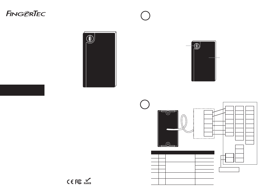
i-Kadex is a slave terminal for a card door access control system. The i-Kadex reads and captures
information from a card, and sends the information to a master terminal for verification. The i-
Kadex communicates with the master terminal via Wiegand 26-bit output and requires a master
terminal with a Wiegand 26-bit input to accept signals from the slave.
Rear of i-Kadex Terminal
Rear of Master Terminal
BEEP
GLED
INWD0
INWD1
GND
+12V
GND
+12V
DC12V 3A Power Supply
Color
Black
Red
Green
White
Black
Grey
Purple
Wire
GND
PWR
WD0
WD1
GND
LED
Beep
Connect to master
Power Supply: GND
Power Supply: +12V
INWD0
INWD1
GND
G LED
BEEP
Function
Supplies power (DC12V 3A)
toi-Kadex
Wiegand 26-bit output connects
to a master terminal’s. Wiegand
26-bit input
LED input from the master
terminal
Buzzer input from the master
terminal.
Connections &
Wiring Diagram
Note:
Only 1 black wire is provided. It can be shared for
GND for power supply and Wiegand 26-bit output.
LED light indicator
Red light: indicates standby
mode
Green light: indicates that the
card information is being read
and sent to the master
terminal for verification.
A Firm Access with
FingerTec
i-Kadex
©
2012
FingerTec Worldwide Sdn. Bhd. All rights reserved • 052012
1
2
Green
White
Black
Red
i-Kadex
BEEP
GLED
RLED
INWD0
INWD1
GND
+12V
485B
485A
GND
232T
232R
GND
WD1
WD0
Purple
Grey
RJ45-1
RJ45-2
RJ45-3
RJ45-4
NC2
COM2
NO2
NC1
COM1
NO1
BUT
GND
SEN
Card scanning area
To scan and receive card
information for verification at
the master reader. Default card
type: RFID Card, 125kHz 40 to
80mm. Made to order: MIFARE,
13.56MHz 30 to 50mm