Attach gear housing covers, Prepare ascent module, Insert upper body tube – Estes 2110 - Outlander User Manual
Page 5: Cut & trim plastics parts, Assemble engine mount
8
5
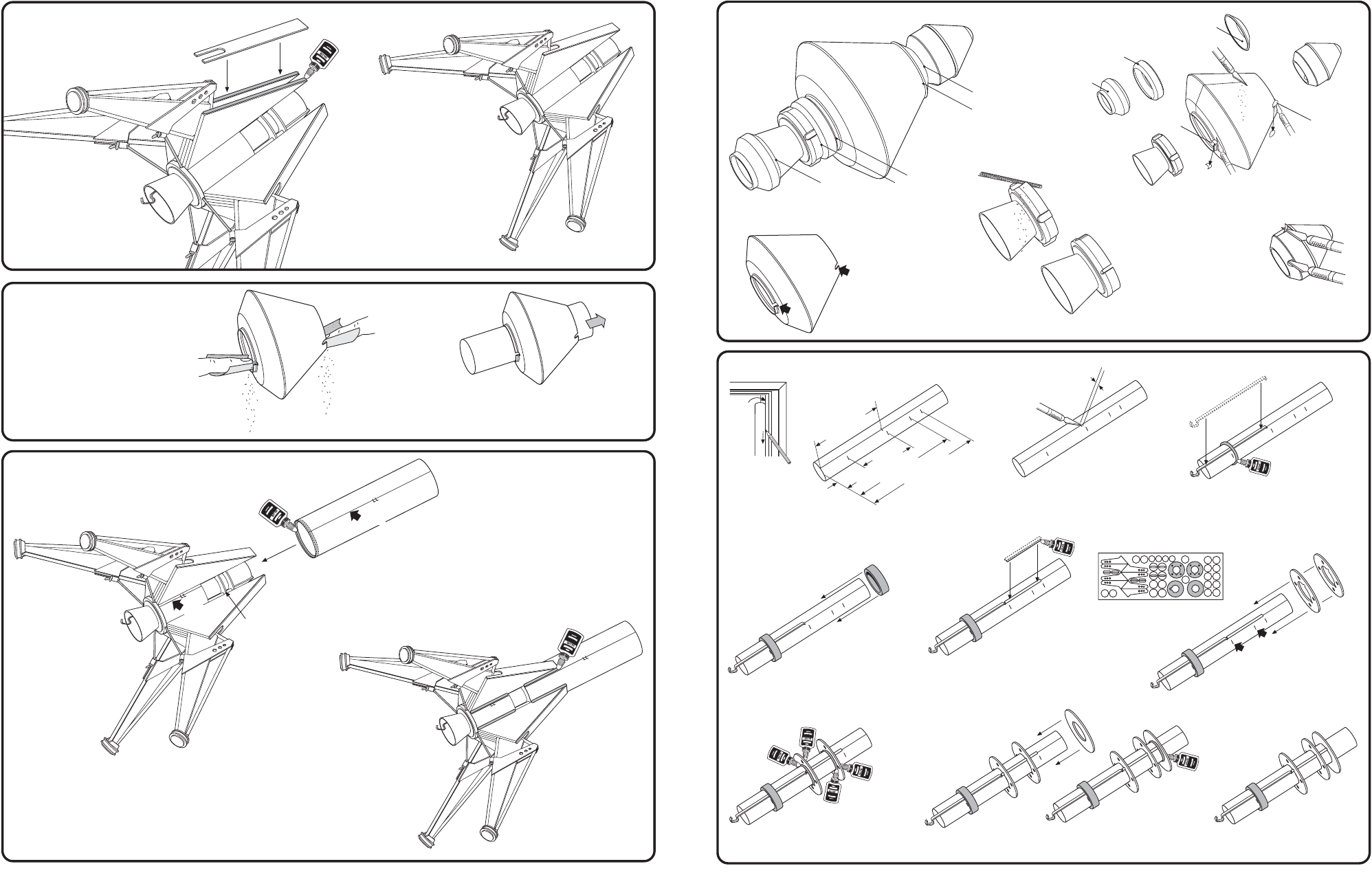
15. ATTACH GEAR HOUSING COVERS
A. Apply Carpenter's Glue
to Gear Housing as
shown. Attach cover.
B. Repeat for other three
legs. Let dry.
COMPLETED
ASSEMBLY
16. PREPARE ASCENT MODULE
A. Apply glue ring just
inside Upper Body
Tube as shown.
A. Sand Ascent Module openings
until Upper Body Tube fits
smoothly.
17. INSERT UPPER BODY TUBE
B. Slide tube over lower assembly
until it is flush with Lower
Centering Ring. Align launch
lug lines. Let Dry.
COMPLETED
ASSEMBLY
6. CUT & TRIM PLASTICS PARTS
CUT
CUT
CUT
CUT
CUT
7. ASSEMBLE ENGINE MOUNT
2 1/2"
(6.4 cm)
1"
(2.5 cm)
2 11/16"
(6.8 cm)
3 9/16"
(9 cm)
3 15/16"
(10 cm)
1/8"
COMPLETED MOUNT
Set aside to dry.
A. Using a razor saw, cut Ascent
Module/Nose Cone where shown.
B. Trim flash using a modeling knife or
sandpaper. Remove the two nibs as
shown for the launch lug holes.
DISCARD
DISCARD
DISCARD
C. Sand until flush.
D. Using a round file,
carefully clean four
slots out of Engine
Nozzle until flush.
COMPLETED
NOZZLE
A. First draw line full length of Engine Mount
Tube using door frame. Measure and mark
tube using a pencil as shown.
DOOR
FRAME
B. Make a 1/8" (3 mm) slit at
the 2 1/2" (6.4 cm) mark.
C. Insert Engine Hook into slit as shown.
Apply bead of glue around tube just
above the 1" (2.5 cm) mark.
D. Slide the green centering
ring down the tube to the
1" (2.5 cm) mark.
E. Glue the small 2" wooden dowel (supplied
pre-cut) to tube straight on line and flush
with end of Engiine Hook. Let dry.
F. Remove centering rings
from die-cut sheet. Sand
any nubs.
G. Slide the two Centering Rings
with holes down to the 2 11/16"
(6.8 cm) and 3 9/16" (9 cm)
marks.
H. Apply glue fillets to both sides
of Centering Rings. Let dry.
I. Slide Centering RIng with no notch over tube up to the
3 15/16" (10 cm) mark. Apply glue filles to both sides.
NOTE: You may want to primer, sand, and paint the
Nozzle and Nose Cone at this time. Don't finish the
Ascent Module yet. See PAINTING GUIDE (page 2).
NOTE: You may want to primer, sand, and paint the Ascent
Module at this time. See PAINTING GUIDE (page 2).
LAUNCH
LUG
HOLE
LAUNCH
LUG
HOLE
LOWER
CENTERING
RIING
C. Apply glue fillets
to Gear Housing
and Body Tube
joints. Smooth
with finger.
ALIGN
ALIGN
E. Using a modeling knife
and round file, clean out
hole in Nose Cone for
Shock Cord and remove
excess flash.
B. Test fit Ascent Module
openings with Upper
Body Tube.