Evacuating, Air purge, Table viii: air purge – Carrier XPOWER 38VYX080 User Manual
Page 10: Vacuum pump
GB - 9
38VYX050/38VYX080
E N G L I S H
Evacuating
- This air conditioner can be installed up to the connecting pipe length and height difference in the following table.
Air Purge
With respect to the preservation of terrestrial environment, adopt
“Vacuum pump” for air purge (Evacuate air in the connecting pipes)
when installing the unit.
• Do not discharge the refrigerant gas to the atmosphere to
preserve the terrestrial environment.
• Use a vacuum pump to discharge the air (nitrogen, etc.) remained
in the set. If the air remains, the capacity may decrease.
For the vacuum pump, be sure to use one with backflow preventer
so that the oil in the pump does not backflow into the pipe of the air
conditioner when the pump stops.
(If oil in the vacuum pump is put in an air conditioner including
R410A, it may cause trouble on the refrigeration cycle.)
Table VIII: Air Purge
Capacity rank
Max. connecting
Height difference (m)
Hexagonal
pipe length (m)
Outdoor unit higher than indoor unit Outdoor unit lower than indoor unit
w
rench size
38 VYX 050
30
30
15
4 mm
38 VYX 080
50
30
15
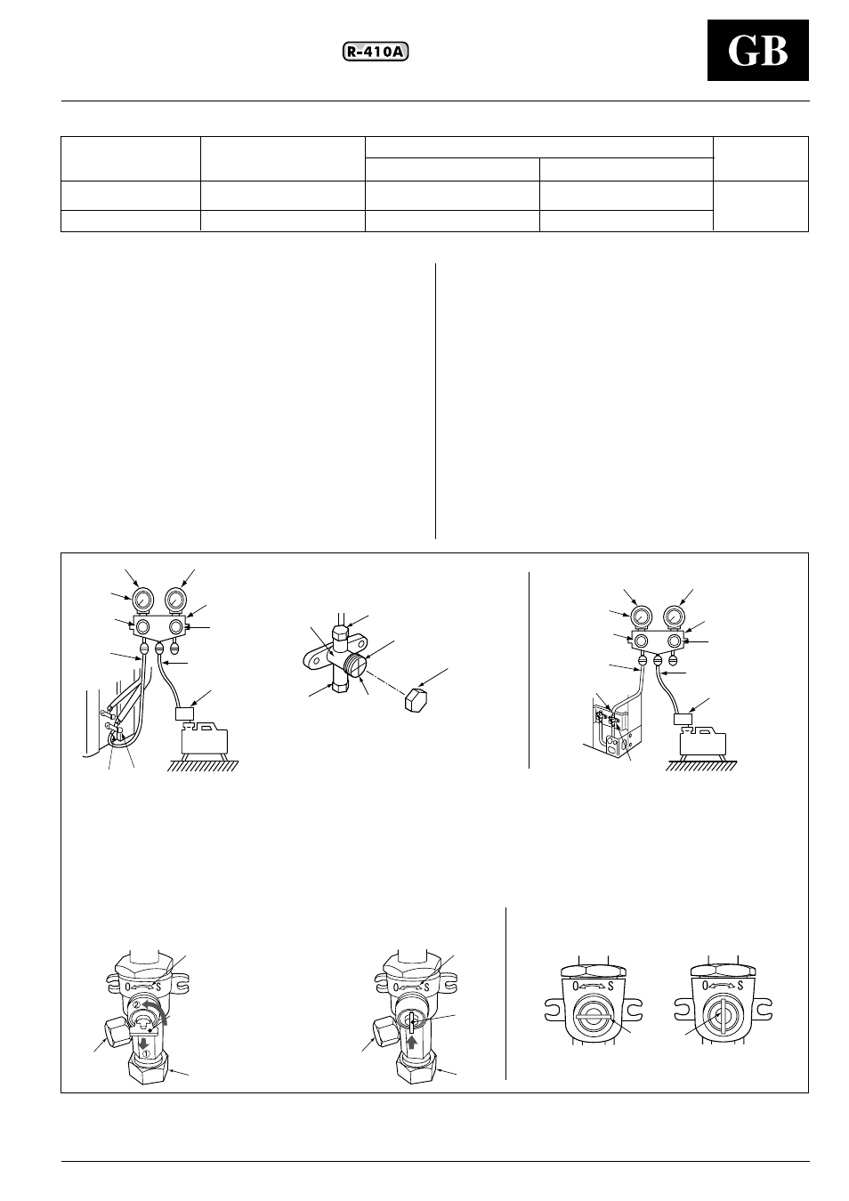
Vacuum pump
• As shown in the right figure, connect the charge hose after the
manifold valves are closed completely.
• Attach the connecting port of the charge hose with a projection to
push the valve core (setting pin) to the charge port of the set.
• Open handle Low fully.
• Turn ON the vacuum pump.
(*1)
• Loosen the flare nut of the packed valve (Gas side) a little to
check the air passes through.
(*2)
• Tighten the flare nut again.
• Execute vacuuming until the compound pressure gauge indicates
–101kPa (–76cmHg).
(*1)
• Close handle Low completely.
• Turn OFF the vacuum pump.
• Leave the vacuum pump as it is for 1 or 2 minutes, and check the
indicator of the compound pressure gauge does not return.
• Open fully the valve stem or the valve handle. (First, at liquid side,
then gas side)
• Disconnect the charge hose from the charge port.
• Tighten valve and caps of the charge port surely.
*1. Use the vacuum pump, vacuum pump adapters, and gauge manifold referring to the manuals attached to each tool before using them. For the vacuum
pump, check oil is filled up to the specified line of the oil gauge.
*2. While the air is purged, check again that the connecting port of charge hose, which has a projection to push the valve core, is firmly connected to the
charge port.
ቢ
Compound pressure gauge
ባ
Pressure gauge
ቤ
Manifold valve
ብ
Handle Hi (Keep fully closed)
ቦ
Charge hose (For R410A only)
ቧ
Vacuum pump adapter for counter-flow prevention
(For R410A only)
ቨ
Charge hose (For R410A only)
ቯ
ተ
ቱ
ቴ
ታ
ቲ
ቢ
ቮ
ቭ
ቨ
ቦ
ብ
ቤ
ባ
ቧ
ቩ
ቫ
ቪ
Close
38VYX050
38VYX080
Open
Handle position
ቩ
Packed valve (Gas side)
ቪ
Vacuum pump
ቫ
Service port (Valve core (Setting pin))
ቭ
Handle Lo
ቮ
-101kPa (-76cmHg)
ቯ
Valve unit
ተ
Flare nut
ቱ
Stopper
ቲ
Charge cap
ታ
Valve rod
ቴ
Charge port
ት
Push in handle.
ቶ
Handle
Pull out the handle and using cutting
pliers, etc. turn it counterclockwise
by 90˚. (Open fully)
ቢ
ባ
ቤ
ብ
ቮ
ቭ
ቨ
ቦ
ቧ
ቩ
ቫ
ቪ
Flexible charge pipe
(only for R410A)
Vacuum pump adapter for
counter-flow prevention
(only for R410A)
Flexible charge pipe
(only for R410A)
ቯ
ተ
ቴ
ቶ
ት
ቯ
ተ
ቴ
ቶ
A
opened
fully
closed
completely
ቶ