7installing the dle-30 on your airplane – DLE 30 User Manual
Page 7
7
Installing the DLE-30 on Your Airplane
Note: The DLE-30 must be installed on at least a 3/8” [9.5mm] fi rewall.
The fi rewall must be securely glued to the airplane. Use triangle
stock and pin the fi rewall with hardwood dowels to reinforce the
fi rewall glue joints. Never install the DLE-30 onto a fi rewall thinner
than specifi ed because it may fail due to the power of the engine.
Note: The length of the engine from the back on the engine mount
to the face of the propeller washer is 6.37” [162mm].
1. Use the supplied template (on the back cover of this manual) to
drill the engine mounting bolt holes.
2. Install the standoffs to the engine
with the included 5 x 25mm SHCS
and 5mm fl at washers (it’s a good
idea to use 5mm lock washers
between the SHCS and the fl at
washers). Next, install the engine
with standoffs to the fi rewall using
(4) 5 x 20mm SHCS with 5mm
lock washers and fl at washers (not included). Use threadlocking
compound, such as Great Planes
®
Pro
™
Threadlocker (GPMR6060)
on all mounting screws.
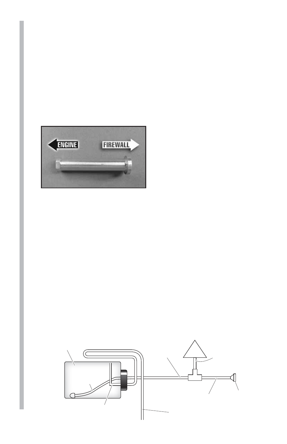
3. Install the fuel tank in the airframe. Use only gasoline approved
fuel tank and fuel lines and a gasoline approved stopper. One line
should go to the carburetor and the other is to be used as a vent (a
vent line is simply an open ended fuel line from the fuel tank which
exits the engine compartment or the fuselage; most vent lines exit at
the bottom of the fi rewall).You can fi ll the tank by using the carburetor
line as fi ll line if you have access to it or install a third line to be used
as fi ll line. Installing a third line is the cleanest and easiest way to add
fuel. An alternative fueling set up is a 2-line system with a T-fi tting
approved for gasoline use. Be sure to use a fi ller plug with either a 2
line or 3 line set-up. It's a good idea to add an extension to the vent
line as shown, that goes up and to the rear of the tank. This helps to
avoid draining fuel from the tank when the model is pointed down.
Drain/Vent Pressure Relief Line
Route to top-front of fuel tank interior,
to prevent siphoning (2-Line Set-up)
T-Fitting
Carb
Clunk Line
Fuel Tank
Filler Cap
or Plug
Supply Line
to T-Fitting
Make connection line
between T-Fitting and
Carburetor as short
as possible.
Fuel fill line
This line must be extended
to exit the bottom of the aircraft.