Digilent ServoMini User Manual
Page 4
Digilent, Inc.
Digilent ServoMini Board Reference Manual
www.digilentinc.com
www.digilentinc.com
4
Copyright Digilent, Inc. All rights reserved. Other product and company names mentioned may be trademarks of their respective owners.
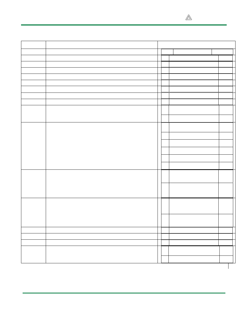
Table 1: I/O connections
Location Description
Pin Function Port/bit
J1 Servo
1
S ADC0 PC0
J2 Servo
2
S ADC1 PC1
J3 Servo
3
S ADC2 PC2
J4 Servo
4
S ADC3 PC3
J5 Servo
5
S AIN1 PD7
J6 Servo
6
S AIN0 PD6
J7 Servo
7
S T1 PD5
J8 Servo
8
S XCK/T0 PD4
J9 & J10 TWI connectors
The ATMEL TWI interface can be accessed on
this connector
1 ADC5/SCL/PCINT13 PC5
2 ADC4/SDA/PCINT12 PC4
J11
SPI interface and in-system-programming
When the shorting block on JP1 IS IN THE SS
position, J11 is used for the SPI port. When the
shorting block on JP1 is in the RST position, J11
is used for in-system-programming.
1 PCINT2/SS/OC1B PB2
2 PCINT3/OC2A/MOSI PB3
3 PCINT4/MISO PB4
4 SCK/PCINT5 PB5
5 GND
6 VCC
J12 Power
supply
When JP2 is shorted, J12 supplies power to both
the MiniServo’s processor and the servos. When
JP2 is left open, J12 only supplies power to the
processor.
1 GND
2 VCC
J13
Screw terminal Power supply
When JP2 is shorted, J13 can supply power to
both the processor and the servos. When JP2 is
left open, J13 becomes the dedicated servo
power supply.
1 SVCC
2 GND
LD1 LED
1
ICP1
PB0
LD2 LED
2
OC1A
PB1
LD3 LED
3
INT1
PD3
Programmable TWI pull-ups
1 XTAL1/TOSC1 PB6
2 XTAL2/TOSC2 PB7