Digilent 410-225P-KIT User Manual
Page 2
PmodOLED2 Reference Manual
www.digilentinc.com
page 2 of 3
Copyright Digilent, Inc. All rights reserved. Other product and company names mentioned may be trademarks of their respective owners.
Power-off sequence:
1. Send Display Off command.
2. Power off VCC.
3. Delay 100ms.
4. Power off VDD.
There are some considerations while operating
the PmodOLED2 while powering the board in
one of the two aforementioned ways.
If the PmodOLED2 is being powered from an
external source (i.e., JP1 is set to EXT), do not
remove, and then reconnect, power to the
PmodOLED2 while the development board is
still powered.
The development board will not
know that the PmodOLED2 has been reset,
and therefore, the correct power-on sequence
will not be executed and the PmodOLED2 may
be damaged.
Gray Scale
The display on the PmodOLED2 is a 4-bit
grayscale display. This means that there are
16 levels of pixel brightness.
The grayscale level data (GS Level) for a pixel
is fetched from one half of a byte (a nibble)
stored in the on board Graphic Display Data
RAM (GDDRAM). The value will range from 0-
15 (0x0
– 0xF).
The value stored in GDDRAM is then decoded
as a pulse width for the pixel’s driving current.
The pulse width values are stored in the Gray
Scale Table, which is defined upon initialization
of the device. This table will hold 16 values
ranging from 0-180. Gray Scale level 0 (pixel
off) is always set to 0, and cannot be changed.
Gray Scale levels 1-15 can have any value
between 0 and 180.
Interface
The display has a D/C pin (display or
command select) that determines whether
bytes sent to the display are interpreted as
commands or as display data. The D/C pin is
set high for display buffer access and low for
command access.
The RES pin is used to reset the SSD1322
display controller. The RES pin is driven low
for reset and driven high for normal operation.
The low-going reset pulse must be a minimum
of 3us (microseconds) in duration for the
display controller to reset correctly.
The UG5664 display has been designed as a
parallel device. The maximum parallel clock
frequency is 3.3MHz. The CS (Chip Select) pin
has to be held low for the display to receive
data over the parallel interface.
Digilent has libraries for the PmodOLED2 that
provide functions for initializing the display and
rendering simple text and graphics onto the
display. These libraries can be used as-is or as
a starting point for a more sophisticated
graphics library. They are available, with
documentation, on the PmodOLED2 product
page at www.digilentinc.com.
The OLED2 display uses a compatible
command set from the SSD1322 device. For
more information, see the SSD1306 datasheet
available at www.solomon-systech.com.
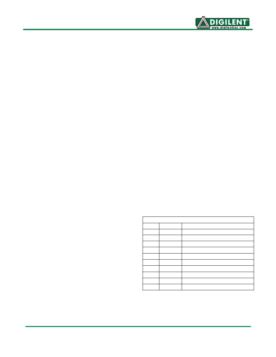
Connector J1
Pin
Signal
Description
1
D0
Parallel data bit 0
2
D1
Parallel data bit 1
3
D2
Parallel data bit 2
4
D3
Parallel data bit 3
7
D4
Parallel data bit 4
8
D5
Parallel data bit 5
9
D6
Parallel data bit 6
10
D7
Parallel data bit 7
5, 11 GND
Power Supply Ground
6, 12 VCC
Power Supply
Interface Connector Signal Description
Interface Connector Signal Description
PmodWifi