Digilent Nanocon User Manual
Digilent Hardware
N
N
a
a
n
n
o
o
c
c
o
o
n
n
™
™
R
R
e
e
f
f
e
e
r
r
e
e
n
n
c
c
e
e
M
M
a
a
n
n
u
u
a
a
l
l
®
w w w . d ig i l en t inc . c om
Revision: February 9, 2009
Note: This document applies to REV A-B of the board.
215 E Main Suite D | Pullman, WA 99163
(509) 334 6306 Voice and Fax
Doc: 502-095
page 1 of 6
Copyright Digilent, Inc. All rights reserved. Other product and company names mentioned may be trademarks of their respective owners.
Overview
The Nanocon board is useful for
embedded control and robotics projects for
both students and hobbyists.
The Nanocon’s versatile design and
programmable microcontroller allows you
to control different external devices and
program the board for multiple uses. The
board has many I/O connectors, power
supply options, and supports a number of
programming tools including ATMEL AVR
®
STUDIO 4, and WinAVR.
The Nanocon has a number of connections
for peripheral devices. Digilent peripheral
modules (Pmods™) include H-bridges,
analog-to-digital and digital-to-analog
converters, a speaker, switches, buttons,
LEDs, RS232 converters, screw terminal
connectors, BNC connectors, servo
motors, and more. For more information
see
www.digilentinc.com
.
Features include:
• ATmega168 microcontroller
• four 6-pin connectors for Digilent
Pmod peripheral module boards
• four LEDs
• ESD protection for all I/O pins
• in-system programming support
using the Digilent parallel JTAG
cable or the Digilent USB JTAG/SPI
cable.
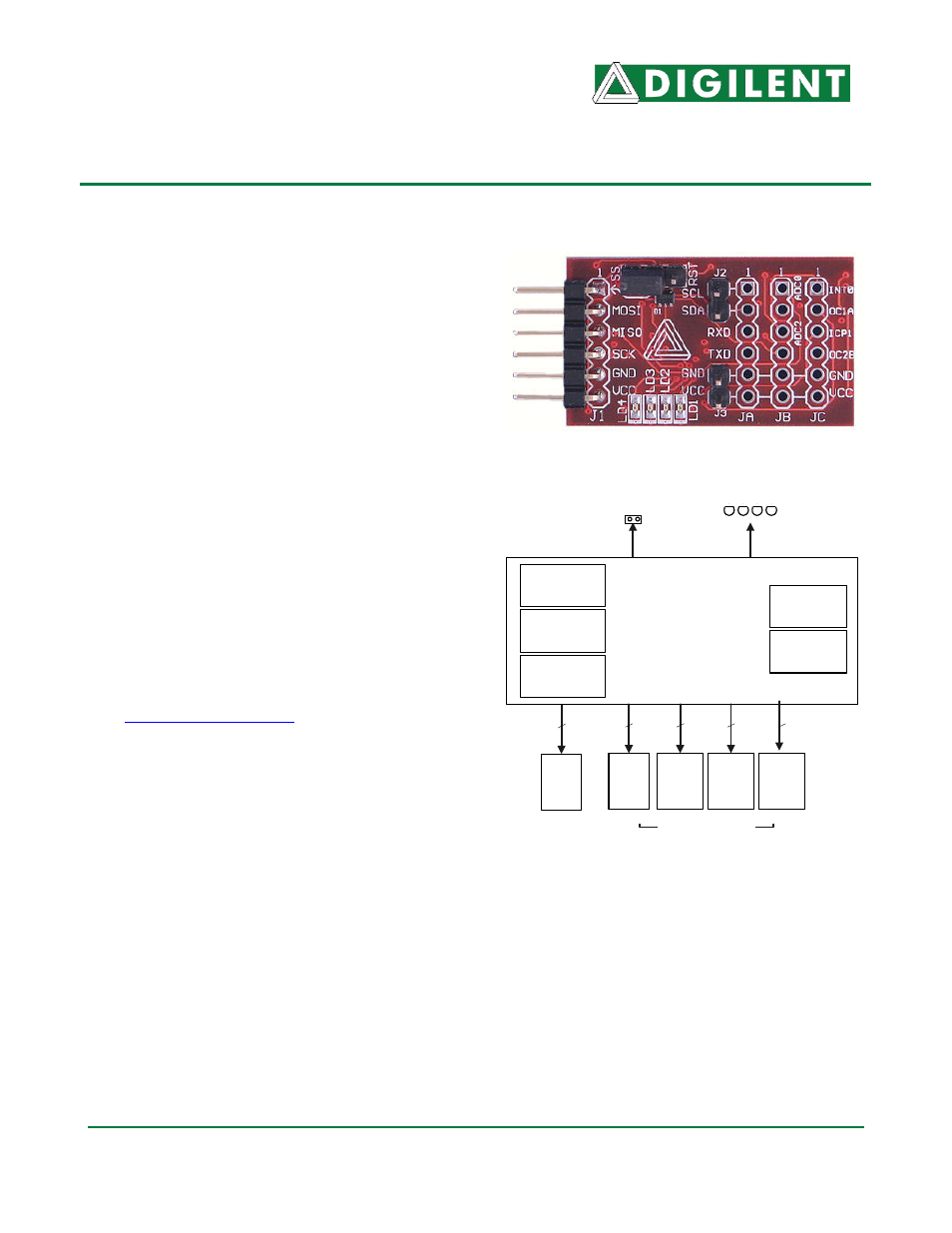
ATMega168
MLF32
Four 6-pin PMOD
connectors
JA
TWI/
RS232
16K Flash
(Internal)
4 LEDs
4
512 EEPROM
(Internal)
Internal
Oscillator
UART, SPI,
& TWI ports
JB
IO
JC
IO
J1
SPI/
ISP
4
4
4
1k SRAM
(Internal)
Nanocon
TM
Power
connector
J2
TWI
2
Nanocon Circuit Diagram