Inter-integrated circuit interface, On-board i2c peripheral devices, The inter-integrated circuit (i2c – Digilent 410-173-KIT User Manual
Page 6: Jumper settings for i2c pull-up resistors
Cerebot 32MX4 Reference Manual
www.digilentinc.com
page 6 of 15
Copyright Digilent, Inc. All rights reserved. Other product and company names mentioned may be trademarks of their respective owners.
servo power bus independent from the VU bus.
In this case, the VS bus is powered from screw
terminal connector J5.
Finally, for very high servo current applications,
a separate power bus external to the Cerebot
32MX4 can be used to provide servo power. In
this case, remove the shorting block on JP1,
tie the external servo power bus ground to the
Cerebot 32MX4 ground through the ground
terminal on J10, and use pin 1 on the servo
connectors to bring the servo control signals
out to the servos. The servo power and
ground connections are made off-board.
The on-board servo power bus can be used to
provide a maximum of 2A to each servo
connector and 5A total to all servo connectors.
Inter-Integrated Circuit Interface
The Inter-Integrated Circuit (I2C
TM
) Interface
provides a medium speed (100K or 400K bps)
synchronous serial communications bus. The
I2C interface provides master and slave
operation using either 7 bit or 10 bit device
addressing. Each device is given a unique
address, and the protocol provides the ability
to address packets to a specific device or to
broadcast packets to all devices on the bus.
See the Microchip documentation for detailed
information on configuring and using the I2C
interface.
The PIC32MX460 microcontroller used on the
Cerebot 32MX4 provides two independent I2C
interfaces. There are two sets of connectors
on the board for access to the two I2C ports.
Connector J6 provides access to I2C port #1
while connector J2 provides access to I2C port
#2.
Each I2C connector provides two positions for
connecting to the I2C signals, power and
ground. By using two-wire or four-wire MTE
cables (available separately from Digilent) a
daisy chain of multiple Cerebot 32MX4 boards
or other I2C-capable boards can be created.
The I2C bus is an open-collector bus. Devices
on the bus actively drive the signals low. The
high state on the I2C signals is achieved by
pull-up resistors when no device is driving the
lines low. One device on the I2C bus must
provide the pull-up resistors. I2C bus #1 has
permananely connected pull-up resistor. I2C
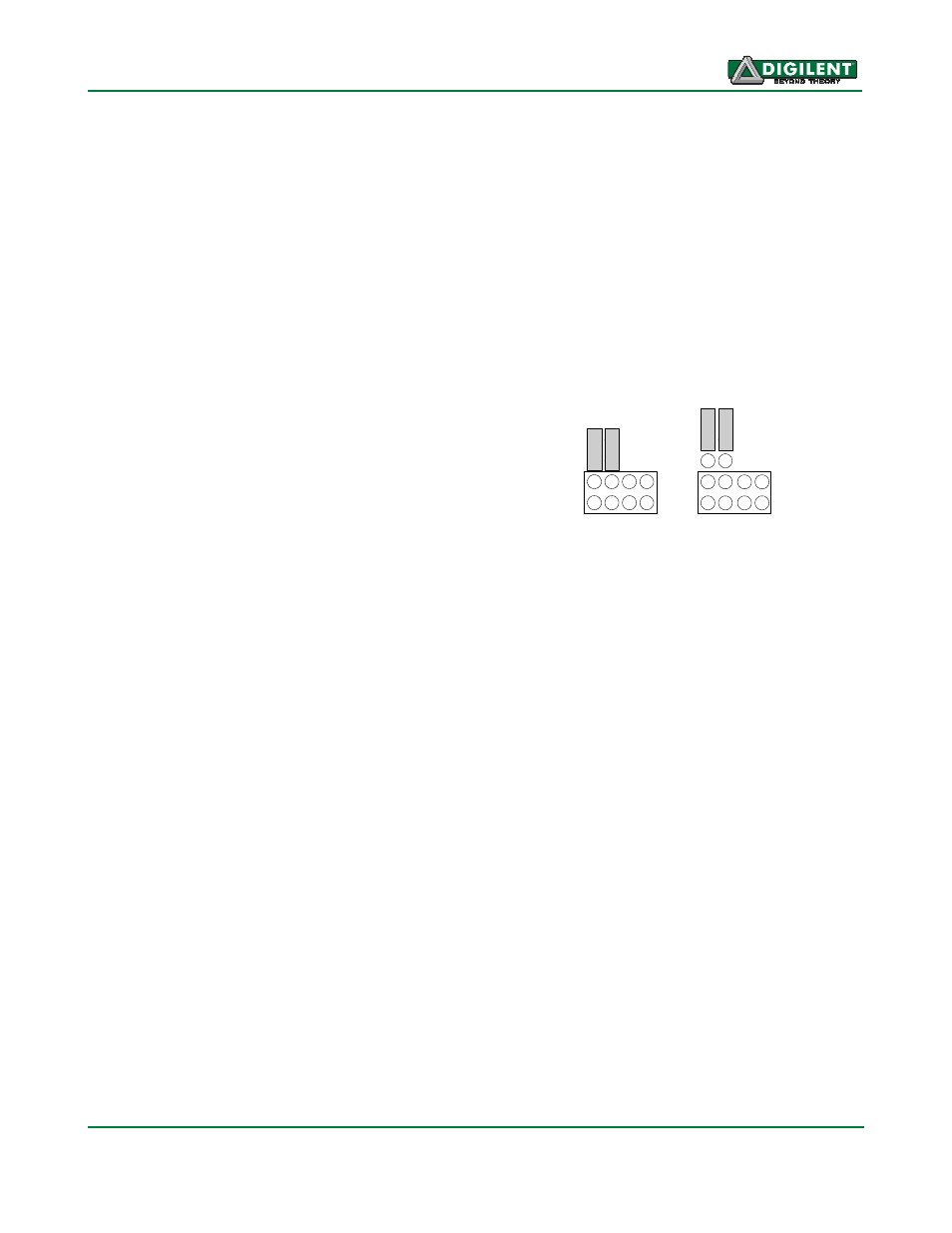
bus #2 provides selectable pull-up resistors
that can be enabled or disabled via jumper
blocks on the ‘pull-up’ positions on connector
J2. The pull-ups are enabled by installing
shorting blocks and are disabled by removing
the shorting blocks. The shorting blocks are
placed so that they line up with the SCL and
SDA labels on the board. Only one device on
the bus should have the pull-ups enabled.
S
C
L
S
D
A
S
C
L
S
D
A
Pull-ups
Enabled
Pull-ups
Disabled
3
V
3
G
N
D
3
V
3
G
N
D
Jumper Settings for I2C Pull-Up Resistors
On-Board I2C Peripheral Devices
The Cerebot 32MX4 provides two on-board
I2C peripheral devices, a 24LC256 serial
EEPROM, and an MCP4725 Digital to Analog
Converter. These devices are both connected
to I2C port #1. The 24LC256 is a 256Kbit
(32Kbyte) serial EEPROM device to provide
non-volatile memory storage. The MCP4725 is
a single channel, 12-bit, serial digital to analog
converter that provides an analog output
voltage for various uses. The device address
for IC2, the 24LC256 is 1010000 (0x50). The
device address for IC3, the MCP4725, is
1100000 (0x60).
Refer to the Microchip data sheets for detailed
information on the operation of these devices.
The analog output voltage from IC3 is available
at two places on the Cerebot 32MX4 board.
The two pin header, J10, provides the DAC
output voltage and ground for connection to