Digilent 210-161P User Manual
Page 4
Digilent, Inc.
FX2 MIB Reference Manual
www.digilentinc.com
www.digilentinc.com
page 4 of 4
Copyright Digilent, Inc. All rights reserved. Other product and company names mentioned may be trademarks of their respective owners.
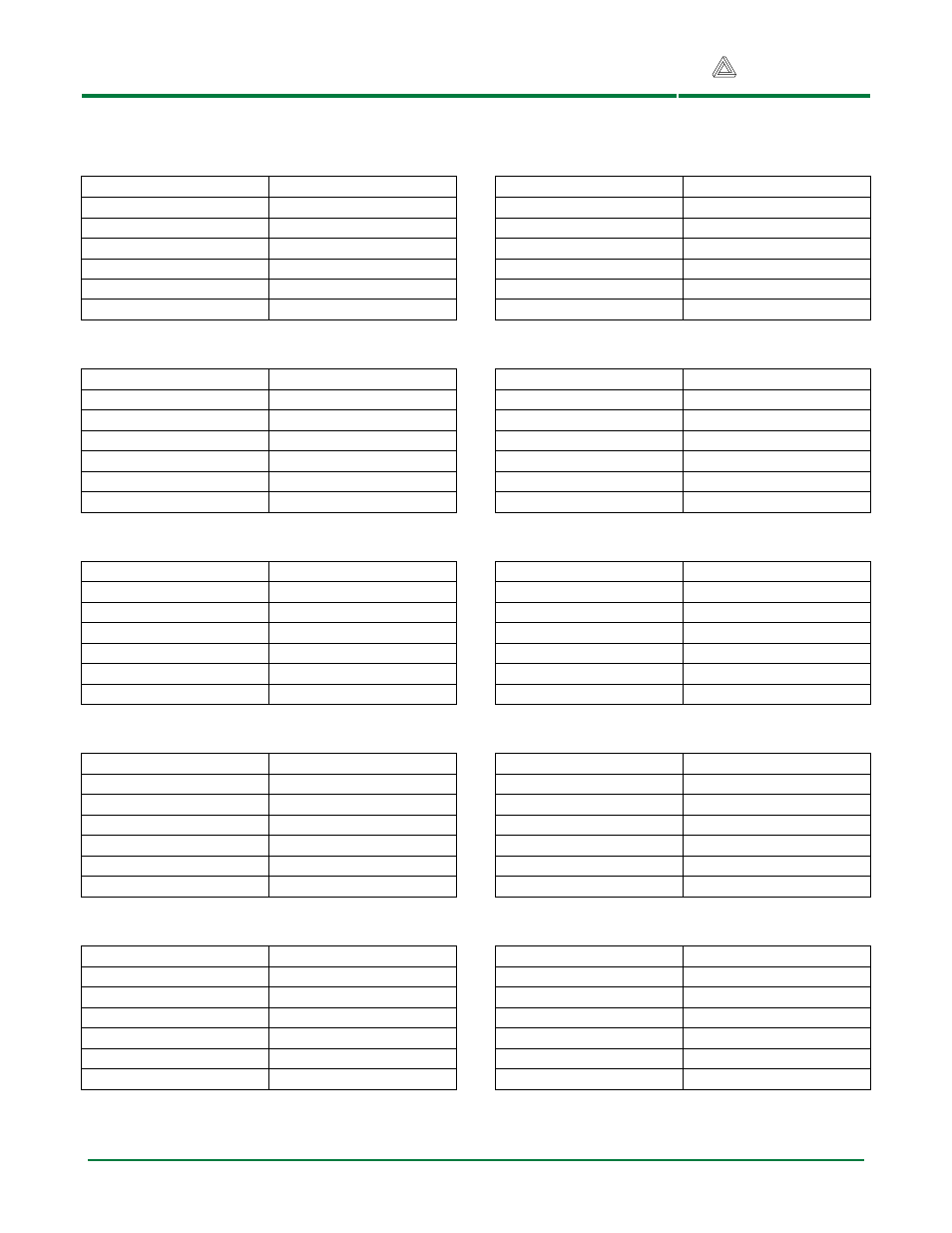
Table 2 Pmod Connector Pin Layouts
J1 Top Set of Pins
Pin
Pinout
1
IO1
2
IO3
3
IO5
4
IO7
5
GND
6
VDD
J2 Top Set of Pins
Pin
Pinout
1
IO9
2
IO11
3
IO13
4
IO15
5
GND
6
VDD
J3 Top Set of Pins
Pin
Pinout
1
IO17
2
IO19
3
IO21
4
IO23
5
GND
6
VDD
J4 Top Set of Pins
Pin
Pinout
1
IO25
2
IO27
3
IO29
4
IO31
5
GND
6
VDD
J5 Pins
Pin
Pinout
1
IO33
2
IO34
3
IO35
4
IO36
5
GND
6
VDD
J1 Bottom Set of Pins
Pin
Pinout
7
IO2
8
IO4
9
IO6
10
IO8
11
GND
12
VDD
J2 Bottom Set of Pins
Pin
Pinout
7
IO10
8
IO12
9
IO14
10
IO16
11
GND
12
VDD
J3 Bottom Set of Pins
Pin
Pinout
7
IO18
8
IO20
9
IO22
10
IO24
11
GND
12
VDD
J4 Bottom Set of Pins
Pin
Pinout
7
IO26
8
IO28
9
IO30
10
IO32
11
GND
12
VDD
J6 Pins
Pin
Pinout
1
IO37
2
IO38
3
IO39
4
IO40
5
GND
6
VDD
- 410-282P-KIT (4 pages)
- 410-279P-KIT (26 pages)
- 410-258P-KIT (16 pages)
- 410-138P-KIT (28 pages)
- 410-178P-KIT (22 pages)
- 410-292P-KIT (29 pages)
- 410-274P-KIT (29 pages)
- 410-182P-KIT (22 pages)
- 410-134P-KIT (17 pages)
- 410-183P-KIT (19 pages)
- 410-155P-KIT (12 pages)
- 6015-410-001P-KIT (26 pages)
- 410-087P-KIT (164 pages)
- 410-146P-KIT (4 pages)
- 6003-410-000P-KIT (138 pages)
- XUPV2P (23 pages)
- 410-047-C2P-KIT (3 pages)
- WaveForms (85 pages)
- 410-297P-KIT (25 pages)
- 410-295P-KIT (37 pages)
- 410-296P-KIT (23 pages)
- 410-209P-KIT REV.D (16 pages)
- 410-209P-KIT REV.C (17 pages)
- 410-254P-KIT (17 pages)
- 410-280P-KIT (9 pages)
- 410-202P-KIT (20 pages)
- 410-273P-KIT (24 pages)
- 410-269P-KIT (11 pages)
- 410-216P-KIT (15 pages)
- 410-231P-KIT (4 pages)
- 410-211P-KIT (10 pages)
- 410-262P-KIT (8 pages)
- 410-229P (7 pages)
- 410-242P-KIT (4 pages)
- 6021-210-000P-KIT (27 pages)
- 410-185P-KIT (21 pages)
- 6032-410-000P-BOARD (4 pages)
- 410-174P (17 pages)
- 410-145P (6 pages)
- 210-264P-BOARD (3 pages)
- 6003-210-012P (27 pages)
- 410-236P-BOARD (2 pages)
- 410-163P (1 page)
- 410-097P-KIT (2 pages)
- 410-255P-KIT (1 page)