Backlight control, Touchscreen, Touch controller – Digilent 210-210P-BOARD User Manual
Page 3
VmodTFT Reference Manual
www.digilentinc.com
page 3 of 5
Copyright Digilent, Inc. All rights reserved. Other product and company names mentioned may be trademarks of their respective owners.
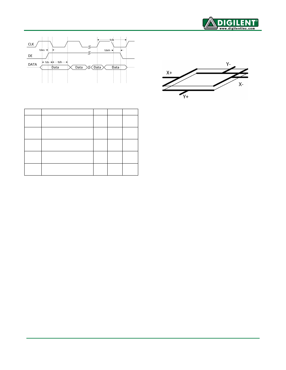
Figure 3 AC Characteristics
Description
Min Max Unit
1/tclk LCD clock
frequency
7
12
MHz
tdes
DE setup before
falling CLK
10
ns
tdeh
DE hold before
falling CLK
10
ns
tds
Data setup before
falling CLK
10
ns
tdh
Data hold before
falling CLK
10
ns
Table 3 LCD Power-Up/Reset Timing
Backlight Control
The LED-EN (TFT_BKLT_O) pin provides
analog or digital control over the backlight
intensity. Jumper JP1 toggles between analog
and digital control.
In analog mode, the backlight intensity is set
by the voltage divider formed by R7 and R10.
Valid values are 0.7V (dimmest) to 1.4V
(brightest).
In digital mode, the FPGA can drive this pin
with a PWM signal of 100Hz-50kHz.
Touchscreen
The four-wire resistive touchscreen is on top of
the LCD. It consists of two conductive
transparent layers, one on top of the other,
separated by a layer of air. These conductive
layers form plates X and Y. Each plate has
electrodes on opposite sides and a constant
resistance.
Figure 4 Touchscreen Plates X and Y
When the screen is touched with sufficient
force, the two plates make contact and form
resistive dividers. By properly biasing the panel
and measuring the voltage on the electrodes,
the coordinates of the touch can be
determined.
For example, tying Y+ and Y- to a power
supply, the voltage on either X+ or X- changes
linearly to the Y coordinate of the touch.
Similarly, supplying power to the X plate and
measuring the voltage on the Y electrode
determines the X coordinate.
Touch Controller
The VmodTFT uses an AD7873 touch
controller to provide an interface for the analog
touchscreen to the FPGA. The controller
supplies current to the touchscreen and
measures the voltage drop using an internal
12-bit analog-to-digital converter. The digitized
voltage values are read back by the FPGA so
the touch coordinates can be determined.
Theoretically, a digitized voltage drop of 000h
(0V) corresponds to a touch very close to the
electrode tied to ground. Likewise, a voltage
drop of FFFh (VCC) corresponds to a touch
very close to the electrode tied to the power
supply. However, the actual values measured
for the VmodTFT are shown in Table 4.