Video timing – Digilent 210-210P-BOARD User Manual
Page 2
VmodTFT Reference Manual
www.digilentinc.com
page 2 of 5
Copyright Digilent, Inc. All rights reserved. Other product and company names mentioned may be trademarks of their respective owners.
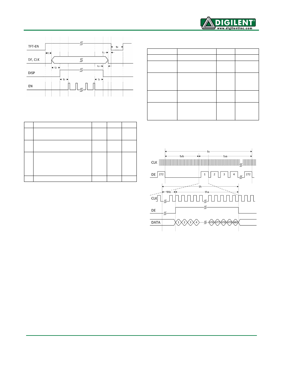
Figure 1 Power-Up Sequence
Description
Min Max Unit
t1 TFT-EN high to first
pixel bus signal
0.05 100
ms
t2 Valid pixel data to DISP
high
0
200
ms
t3 DISP high to backlight
on;
backlight off to DISP
low
160
ms
t4 TFT-EN low pulse
100
ms
Table 1 Power-Up/Reset Timing
Video Timing
To display an image, the LCD needs to be
continuously driven with properly-timed data.
This data consists of the lines and blanking
periods that form video frames. Each frame
consists of 272 active lines and several vertical
blanking lines. Each line consists of 480 active
pixel periods and several horizontal blanking
periods.
Parameter Description
Value Unit
fCLK
Pixel clock
9
MHz
tVA
Vertical active
period
272
lines
tVB
Vertical
blanking
period
16
lines
tHA
Horizontal
active period
480
CLK
periods
tHB
Horizontal
blanking
period
45
CLK
periods
Table 2 Typical LCD Video Timing Parameters
Figure 2 Video Timing
Video data is sent on a parallel interface
synchronous to CLK. The table below lists the
timing parameters of this interface. “Data”
refers to the combined pixel data from the R,
G, and B pins.