Keyboard and mouse interface, Keyboard – Digilent 410-094P User Manual
Page 2
PS/2 Reference Manual
Digilent, Inc.
www.digilentinc.com
page 2 of 4
Copyright Digilent, Inc. All rights reserved. Other product and company names mentioned may be trademarks of their respective owners.
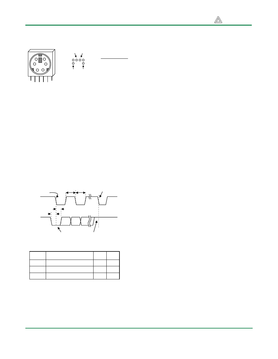
Keyboard and Mouse Interface
PS/2
Connector
Pin 1
Pin 5
Pin 6
Bottom-up
hole pattern
Pin Definitions
Pin Function
1 Data
2 Reserved
3 GND
4 Vdd
5 Clock
6 Reserved
1
5
3
2
4
6
Pin 2
The keyboard and mouse both use identical
signal timings. Both use 11-bit words that
include a start, stop, and odd parity bit, but the
data packets are organized differently, and the
keyboard interface allows bi-directional data
transfers (so the host device can illuminate
state LEDs on the keyboard). Bus timings are
shown below. The clock and data signals are
only driven when data transfers occur, and
otherwise they are held in the “idle” state at
logic ‘1’. The timings define signal
requirements for mouse-to-host
communications and bi-directional keyboard
communications.
T
CK
T
SU
Edge 0
Edge 10
CLK
DATA
T
HLD
T
CK
'1' stop bit
'0' start bit
T
CK
T
SU
Clock time
Data-to-clock setup time
30us
5us
50us
25us
Symbol
Parameter
Min
Max
T
HLD
Clock-to-data hold time
5us
25us
Keyboard
The keyboard uses open-collector drivers so that
either the keyboard or an attached host device
can drive the two-wire bus (if the host device will
not send data to the keyboard, then the host can
use simple input-only ports).
PS/2-style keyboards use scan codes to
communicate key-press data (nearly all
keyboards in use today are PS/2 style). Each
key has a single, unique scan code that is sent
whenever the corresponding key is pressed. If
the key is pressed and held, the scan code will
be sent repeatedly once every 100ms or so.
When a key is released, an “F0” key-up code is
sent, followed by the scan code of the released
key. If a key can be “shifted” to produce a new
character (like a capital letter), then a shift
character is sent in addition to the original scan
code, and the host device must determine which
character to use. Some keys, called extended
keys, send an “E0” ahead of the scan code (and
they may send more than one scan code). When
an extended key is released, an “E0 F0” key-up
code is sent, followed by the scan code. Scan
codes for most keys are shown in the keyboard
diagram below.
A host device can also send data to the
keyboard. Below is a short list of some oft-used
commands.
ED Set Num Lock, Caps Lock, and Scroll Lock
LEDs. After receiving an “ED”, the keyboard
returns an “FA”, then the host sends a byte to
set LED status. Bit 0 sets Scroll Lock, bit 1 sets
Num Lock; and Bit 2 sets Caps lock. Bits 3 to 7
are ignored.
EE Echo. Upon receiving an echo command, the
keyboard replies with “EE”.
F3
Set scan code repeat rate. The keyboard
acknowledges receipt of an “F3” by returning an
“FA”, after which the host sends a second byte
to set the repeat rate.
FE
Resend. Upon receiving FE, the keyboard re-
sends the last scan code sent.
FF
Reset. Resets the keyboard.