Digilent 410-094P User Manual
Digilent Hardware
D
D
i
i
g
g
i
i
l
l
e
e
n
n
t
t
P
P
m
m
o
o
d
d
P
P
S
S
/
/
2
2
™
™
M
M
o
o
d
d
u
u
l
l
e
e
B
B
o
o
a
a
r
r
d
d
R
R
e
e
f
f
e
e
r
r
e
e
n
n
c
c
e
e
M
M
a
a
n
n
u
u
a
a
l
l
®
www.digilentinc.com
Revision: August 3, 2006
215 E Main Suite D | Pullman, WA 99163
(509) 334 6306 Voice and Fax
Doc: 502-094
page 1 of 4
Copyright Digilent, Inc. All rights reserved. Other product and company names mentioned may be trademarks of their respective owners.
Overview
The Digilent PmodPS/2 module board allows a
Digilent system board to send and receive
signals from a PS/2-style keyboard or mouse.
The PS/2 is designed for use with either a
Digilent programmable logic system board or a
Digilent embedded control system board.
Features include:
• a 6-pin header for connection to a
system board
• PS/2 connector for a keyboard or
mouse
• power routing jumpers
Functional Description
The PS/2 has a 6-pin header for easy
connection to a Digilent system board. Most of
Digilent’s programmable logic system boards
(like the Nexys™ or Basys™ boards) or
Digilent’s embedded control boards (like the
Cerebot™) have 6-pin connectors that allow
direct connection of the PS/2. To connect the
PS/2 to some older Digilent system boards, a
Digilent Modular Interface Board (MIB) and a
6-pin cable may be needed. The MIB plugs
into the system board, and the cable connects
the MIB to the PS/2.
Power to the keyboard or mouse can be
provided from the system board or an external
power supply. To power the keyboard or
mouse from the system board, set the shorting
block on jumper JP2 to the VB position. To
power the keyboard or mouse from an external
power supply, set the shorting bock on JP2 to
the VE position and attach the external power
supply to JP1. The external supply voltage is
attached to the VE pin of JP1 and the ground
for the external power supply is attached to the
GND pin of JP1.
NOTE: Some keyboards and mice can operate
with a 3.3V power supply but some require a 5V
power supply. Be careful to observe the correct
polarity when connecting an external power
supply to JP1 and do not use an external power
supply voltage greater than 5V.
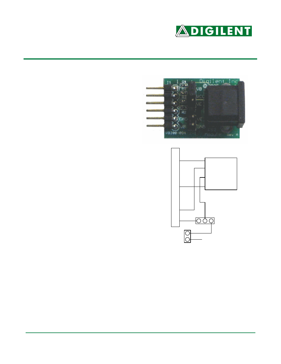
GND
VCC
PmodPS/2 Circuit Diagram
J1
Connec
tion
PS/2
Connector
Data
CLK
P2
P4
GND
VCC
GND
VCC
JP2
JP1
External Power