Digilent 410-237P User Manual
Digilent Hardware
P
P
m
m
o
o
d
d
G
G
P
P
S
S
™
™
R
R
e
e
f
f
e
e
r
r
e
e
n
n
c
c
e
e
M
M
a
a
n
n
u
u
a
a
l
l
Revision:
September 06, 2012
Note:
This document applies to REV A of the board.
1300 NE Henley Court, Suite 3
Pullman, WA 99163
(509) 334 6306 Voice | (509) 334 6300 Fax
Doc: 502-237
page 1 of 4
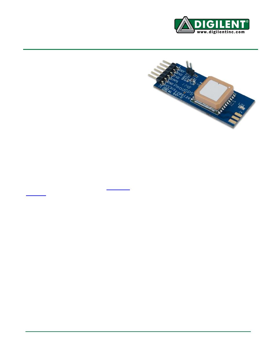
Overview
The PmodGPS can add satellite positioning
accuracy to any embedded system. The
PmodGPS features a GlobalTop Gms-u1LP
GPS antenna module that utilizes the
MediaTek GPS MT3329.
Functional Description
The PmodGPS uses a standard 6-pin
connector and communicates via a 2-wire
Universal Asynchronous Receiver/Transmitter
(UART.) The PmodGPS also has a 2-pin
connector for control of the NRST pin to the
module and the Radio Technical Commission
for Maritime services, or RTCM pin for
Differential Global Positioning System (DGPS)
data using RTCM protocols.
Note: The PmodGPS arrives with the RTCM
feature inactive, to enable RTCM capabilities
users should contact GlobalTop at
Interface
The PmodGPS uses UART protocol for data
transmission and reception. The interface
operates at a default baud rate of 9.6 kBd, 8
data bits, no parity, and with single stop bits.
However, users can change the baud rate to
predefined values that range from 4.8 kBd to
115.2 kBd.
The reset pin (NRST) on J2 allows normal
operation in active low. If users toggle the
NRST pin it will completely reset the module.
This reset performs similar to a power cycling
of the device. The 1 PPS pin on J1 provides a
one pulse-per-second output synchronized
with GPS time. (See the timing diagram in
figure one)
Features include:
Integrated ceramic GPS antenna
Standard UART interface
Input voltage: 3V
– 3.6V
A 10Hz maximum update rate (1Hz Default
rate)
3m 2D accuracy without aid
Low power consumption (24mA tracking
and 30mA during acquisition)
Ultra-high sensitivity: -165dBm
A 515m/s maximum velocity and 18,000m
maximum altitude
Auto switchover to external antenna
12.5mm coin cell retainer for battery
backup of GPS, RTCC, and almanac
The 3DF pin on J1 indicates the status of the
user’s positional fix. When the module has a
constant fix (2D or 3D) this pin stays low, if the
module is unable to get a fix then the pin will
toggle every second. (See figure two) LD1
also follows this same behavior pattern in order
to give the user a visual representation.