Jumper settings – Digilent 410-259P User Manual
Page 2
PmodDHB1™ Reference Manual
®
www.digilentinc.com
www.digilentinc.com
Copyright Digilent, Inc.
page 2 of 3
The quadrature encoder signals are a pair of
square waves whose frequency is proportional
to motor rotation speed and with the pulses 90°
out of phase. You can determine the motor
speed with the frequency and motor rotation
direction by the phase relationship between the
two signals.
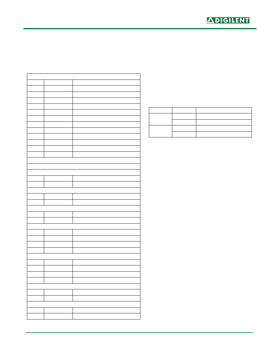
Jumper Settings
Jumpers JP1 and JP2 allow both h-bridge
outputs to be run from the same enable and
direction pins. This allows the two bridge
outputs to be operated in parallel to drive a
single motor with twice the current. Refer to
Table 3 for available settings.
Jumper Setting
Description
JP1
1
Motor 2 Uses EN1
3
Motor 2 Uses EN2
JP2
1
Motor 2 Uses DIR1
3
Motor 2 Uses DIR2
Table 3: Set Jumper Description
Pulse Width Modulation and Motor
Speed Control
Operators can control motor speed by varying
the input voltage to a circuit. However, you
can only apply a logic high or logic low signal
to the motor in a digital circuit. There are only
two ways to control a dc motor digitally. Either
use a variable resistance circuit to control the
motor voltage, or pulse the power to the motor.
Since variable resistance circuitry is expensive,
complicated, and energy inefficient because of
heat loss, Digilent recommends controlling
motor speed through pulse width modulation
(PWM).
Pulse width modulation is a digital method of
transmitting an analog signal. Even though
PWM is not a clean source of DC output
voltage, it controls motors well.
Figures 1 through 3 illustrate a PWM system
with an input frequency of 2KHz. You control
the motor speed by adjusting the time each
wave remains at peak output power. Figure 1
demonstrates a 10% “duty cycle,” where the
signal is logic high for only 1/10 of a
wavelength. This 10% positive peak is equal to
10% of the total 3.3V input, or 0.33V. (See
Connector J1 – H-Bridge Interfaces
Pin
Signal
Description
1
EN1
Motor 1 Enable
2
DIR1
Motor 1 Direction
3
S1A
Motor 1 Sensor A Feedback
4
S1B
Motor 1 Sensor B Feedback
5
GND
Power Supply Ground
6
VCC
Power Supply (3.3V)
7
EN2
Motor 2 Enable
8
DIR2
Motor 2 Direction
9
S2A
Motor 2 Sensor A Feedback
10
S2B
Motor 2 Sensor B Feedback
11
GND
Power Supply Ground
12
VCC
Power Supply (3.3V)
Connector J2- M1 JST 6-Pin Motor Connector
Connector J3- M1 JST 6-Pin Motor Connector
Connector J4- VM
1
VM
Motor Power
2
GND
Power Supply Ground
Connector J5- M1 Power
1
M1+
Motor 1 Positive Supply
2
M1-
Motor 1 Negative Supply
Connector J6- M2 Power
1
M2+
Motor 2 Positive Supply
2
M2-
Motor 2 Negative Supply
Connector J7- M1 Feedback
1
SA1-IN
Sensor A From Motor 1
2
SB1-IN
Sensor B From Motor 1
3
GND
Power Supply Ground
4
VCC
Power Supply (3.3V)
Connector J8- M2 Feedback
1
SA2-IN
Sensor A From Motor 2
2
SB2-IN
Sensor B From Motor 2
3
GND
Power Supply Ground
4
VCC
Power Supply (3.3V)
Connector J9- Fault
1
NFAULT
Overcurrent Condition
2
GND
Power Supply Ground
Connector J10- Sleep
1
NSLEEP
Puts device into sleep state
2
GND
Power Supply Ground
Table 2: Connector Descriptions