Digilent 410-113P User Manual
Digilent Hardware
D
D
i
i
g
g
i
i
l
l
e
e
n
n
t
t
P
P
m
m
o
o
d
d
D
D
A
A
2
2
™
™
D
D
i
i
g
g
i
i
t
t
a
a
l
l
T
T
o
o
A
A
n
n
a
a
l
l
o
o
g
g
M
M
o
o
d
d
u
u
l
l
e
e
C
C
o
o
n
n
v
v
e
e
r
r
t
t
e
e
r
r
B
B
o
o
a
a
r
r
d
d
R
R
e
e
f
f
e
e
r
r
e
e
n
n
c
c
e
e
M
M
a
a
n
n
u
u
a
a
l
l
®
w w w . d i g i l e n t i n c . c o m
Revision: September 25, 2006
215 E Main Suite D | Pullman, WA 99163
(509) 334 6306 Voice and Fax
Doc: 502-113
page 1 of 2
Copyright Digilent, Inc. All rights reserved. Other product and company names mentioned may be trademarks of their respective owners.
Figure 1
Digilent PmodDA2
Overview
The Digilent PmodDA2 Digital to Analog
Module Converter, converts signals from digital
values to analog voltages on two channels
simultaneously with twelve bits of resolution.
The PmodDA2 uses a 6-pin header connector
and, at less than one square inch, is small
enough to be located where the reconstructed
signal is required.
Features include:
• two
National
Semiconductor
DAC121S101, 12-bit D/A converters
• a 6-pin header and 6-pin connector
• two simultaneous D/A conversion
channels
• very low power consumption
• small form factor (0.80” x 0.80”).
Functional Description
The PmodDA2 can produce an analog output
ranging from 0-3.3 volts when operated with a
3.3V power supply. It has two simultaneous
D/A conversion channels, each with a 12-bit
converter that can process separate digital
signals.
The PmodDA2 is equipped with two
DAC121S101 digital to analog converters.
Sending commands via the
SPI/MICROWIRE™ serial bus to the D/A
converters produces outputs. The two
converters are connected in parallel so that
commands are sent to both converters
simultaneously.
The PmodDA2 is designed to work with either
Digilent programmable logic system boards or
embedded control system boards. Most
Digilent system boards, such as the Nexys,
Basys, or Cerebot, have 6-pin
connectors that allow the PmodDA2 to plug
directly into the system board or to connect via
a Digilent six-wire cable
Some older Digilent boards may need a
Digilent Module Interface Board (MIB) and a 6-
pin cable to connect to the PmodDA2. The MIB
plugs into the system board and the cable
connects the MIB to the PmodDA2.
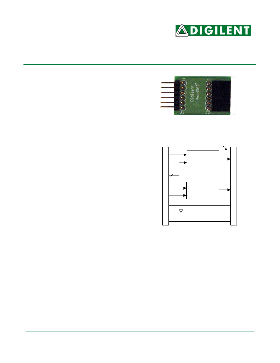
GND
VCC
DAC121S101
D/A
Converter
DAC121S101
D/A
Converter
D2
D1
2
Sync,
Clock
Analog Outputs
J
1
Con
nec
to
r
J
2
Co
nne
c
tor
Figure 2
Block Diagram