Digilent 410-142P User Manual
Page 4
PmodCLP Reference Manual
Digilent, Inc.
www.digilentinc.com
www.digilentinc.com
page 4 of 5
Copyright Digilent, Inc. All rights reserved. Other product and company names mentioned may be trademarks of their respective owners.
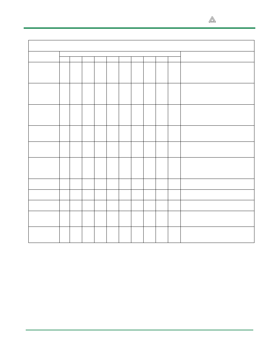
Table 3. LCD Instructions and Codes
Instruction
Instruction bit assignments
Description
RS R/W DB7 DB6 DB5 DB4 DB3 DB2 DB1 DB0
Clear
Display
0
0
0
0
0
0
0
0
0
1
Clear display by writing a 20H to
all DDRAM locations; set DDRAM
address register to 00H; and
return cursor to home.
Return
Home
0
0
0
0
0
0
0
0
1
X
Return cursor to home (upper left
corner), and set DDRAM address
to 0H. DDRAM contents not
changed.
Entry mode
set
0
0
0
0
0
0
0
1
I/D
SH
I/D = ‘1’ for right-moving cursor
and address increment; SH = ‘1’
for display shift (direction set by
I/D bit).
Display
ON/OFF
control
0
0
0
0
0
0
1
D
C
B
Set display (D), cursor (C), and
blinking cursor (B) on or off.
Cursor or
Display shift
0
0
0
0
0
1
S/C R/L X
X
S/C = ‘0’ to shift cursor right or
left, ‘1’ to shift entire display right
or left (R/L = ‘1’ for right).
Function Set 0
0
0
0
1
DL
N
F
X
X
Set interface data length (DL = ‘1’
for 8 bit), number of display lines
(N = ‘1’ for 2 lines), display font (F
= ‘0’ for 5x 8 dots)
Set CGRAM
Address
0
0
0
1
AC5 AC4 AC3 AC2 AC1 AC0
Set CGRAM address counter
AC5 – AC0
Set DDRAM
address
0
0
1
AC6 AC5 AC4 AC3 AC2 AC1 AC0
Set DDRAM address counter
AC6 – AC0
Read busy
flag/address
0
1
BF AC6 AC5 AC4 AC3 AC2 AC1 AC0
Read busy flag (BF) and address
counter AC6 – AC0
Write data to
RAM
1
0
D7
D6
D5
D4
D3
D2
D1
D0
Write data into DDRAM or
CGRAM, depending on which
address was last set
Read data
from RAM
1
1
D7
D6
D5
D4
D3
D2
D1
D0
Read data from DDRAM or
CGRAM, depending on which
address was last set