Digilent 410-142P User Manual
Page 3
PmodCLP Reference Manual
Digilent, Inc.
www.digilentinc.com
www.digilentinc.com
page 3 of 5
Copyright Digilent, Inc. All rights reserved. Other product and company names mentioned may be trademarks of their respective owners.
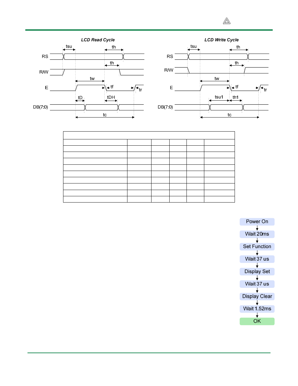
A startup sequence with specific timings is required to ensure proper LCD operation.
This sequence is defined in detail in the Samsung KS0066U data sheet, and
reproduced here for convenience.
After power-on, at least 20ms must elapse before the function-set instruction code
can be written to set the bus width, number of lines, and character patterns (8-bit
interface, 2 lines, and 5x8 dots are appropriate). After the function-set instruction, at
least 37us must elapse before the display-control instruction can be written (to turn
the display on, turn the cursor on or off, and set the cursor to blink or no blink). After
another 37us, the display-clear instruction can be issued. After another 1.52ms, the
entry-mode instruction can set address increment (or address decrement) mode, and
display shift mode (on or off). After this sequence, data can be written into the
DDRAM to cause information to appear on the display.
Note that other compatible LCD controllers use similar start-up sequences which may
not use the same timings as the Samsung controller.
Table 2. LCD Bus Timings
Parameter
Symbol
Min
Max
Unit
Test Pin
Enable cycle time
tc
500
ns
E
Enable High pulse width
tw
220
ns
E
Enable rise/fall time
tr, tf
25
ns
E
RS, R/W setup time
tsu
40
ns
RS, R/W
RS, R/W hold time
th
10
ns
RS, R/W
Read data output delay
tD
60
120
ns
DB0-DB7
Read data hold time
tDH
20
ns
DB0-DB7
Write data setup time
tsu1
40
ns
DB0-DB7
Write data hold time
th1
10
ns
DB0-DB7
LCD startup
sequence