3 fmc support – Digilent 210-264P-BOARD User Manual
Page 3
FMC-HDMI Reference Manual
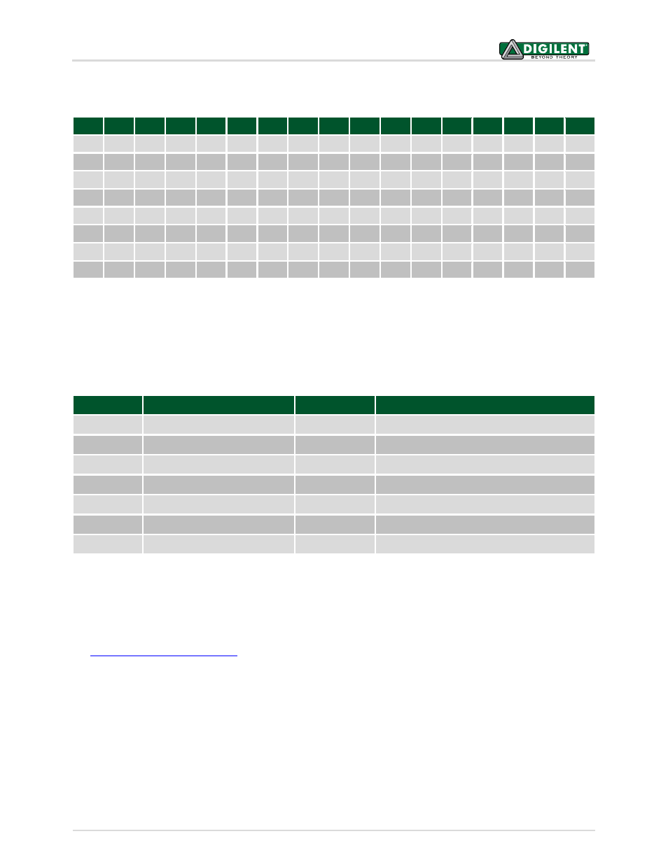
An on-board pre-programmed EEPROM is connected to the DDC (Display Data Channel) bus of the HDMI2 port.
The following EDID (Extended Display Identification Data) is programmed in the factory:
00
01
02
03
04
05
06
07
08
09
0A
0B
0C
0D
0E
0F
00
0x00
0xFF
0xFF
0xFF
0xFF
0xFF
0xFF
0x00
0x10
0xEC
0x00
0x01
0x00
0x00
0x00
0x00
10
0xFF
0x16
0x01
0x03
0x81
0x33
0x1D 0x78
0x02
0x01
0xF1
0xA2 0x57
0x52
0x9F
0x27
20
0x0A 0x50
0x54
0xBF
0xEF
0x80
0x01
0x01
0x01
0x01
0x01
0x01
0x01
0x01
0x01
0x01
30
0x01
0x01
0x01
0x01
0x01
0x01
0x01
0x1D 0x00
0x72
0x51
0xD0 0x1E
0x20
0x6E
0x28
40
0x55
0x00
0x00
0xD0 0x52
0x00
0x00
0x1E
0x00
0x00
0x00
0xFC
0x00
0x44
0x69
0x67
50
0x69
0x6C
0x65
0x6E
0x74
0x20
0x48
0x44
0x4D 0x49
0x00
0x00
0x00
0x10
0x00
0x00
60
0x00
0x00
0x00
0x00
0x00
0x00
0x00
0x00
0x00
0x00
0x00
0x00
0x00
0x00
0x00
0x10
70
0x00
0x00
0x00
0x00
0x00
0x00
0x00
0x00
0x00
0x00
0x00
0x00
0x00
0x00
0x00
0x0E
Table 2. EEPROM pre-programmed content.
The EEPROM can be freely re-written through the J4 header holes and 6-pin Pmod cable. During EEPROM
programming, power to the EEPROM is provided by pin 6 of J4, so make sure there is no HDMI cable plugged in at
the same time.
Below are the pin-outs from the AD8195 Buffer and other HDMI2 port signals to the FMC connector:
FMC Pin
HDMI2 Function
FMC Pin
HDMI2 Function
LA06_P
HDMI2_D0_P
LA01_N_CC
HDMI2_CLK_N
LA06_N
HDMI2_D0_N
LA13_P
HDMI2_SCL
LA05_P
HDMI2_D1_P
LA13_N
HDMI2_SDA
LA05_N
HDMI2_D1_N
LA09_P
HDMI2_PE_EN
LA10_P
HDMI2_D2_P
LA09_N
HDMI2_TX_EN
LA10_N
HDMI2_D2_N
LA17_N_CC
HDMI2_HPA
LA01_P_CC
HDMI2_CLK_P
LA18_N_CC
HDMI2_CEC_OUT
Table 3. HDMI2-FMC pin mapping.
WARNING: VADJ must be 3.3V to properly use the buffer on HDMI2. The TX_EN pin is held low by default, so the
buffer is disabled on power-up. With the buffer disabled, VADJ can be in the range of (1.8V-3.3V).
Note: For more information on the AD8195, see ADI datasheets available online
2.3 FMC Support
The FMC-HDMI uses a Samtec ASP-134604-01 low pin-count male connector as the main connector for digital
signals. The board fully conforms to the VITA 57.1 specs. The connector supports the full range of 1.8V-3.3V bank
supply voltages (VADJ).
The EEPROM with designator IC2 (see board schematic) serves as the IPMI EEPROM, providing hardware definition
information. For more information, consult the VITA 57.1 specs.
Copyright Digilent, Inc. All rights reserved.
Other product and company names mentioned may be trademarks of their respective owners.
Page 3 of 3