Digilent two wire serial interface (dtwi), Private i2c bus, Jumper settings for i2c pull-up resistors – Digilent 410-174P User Manual
Page 7
USB I/O Explorer Reference Manual
www.digilentinc.com
page 7 of 17
Copyright Digilent, Inc. All rights reserved. Other product and company names mentioned may be trademarks of their respective owners.
The on-board servo power bus can be used to
provide a maximum of 2A to each servo
connector and 5A total to all servo connectors.
Digilent Two Wire Serial Interface
(DTWI)
The Digilent Two Wire Serial Interface (DTWI)
provides a medium speed serial comunications
interface compatible with the Inter-Integrated
Circuit (I2C
TM
) Interface defined by Philips. The
I2C interface provides master and slave
operation using 7 bit device addressing. Each
device is given a unique address, and the
protocol provides the ability to address packets
to a specific device or to broadcast packets to
all devices on the bus.
Access to the DTWI bus is provided using the
DTWI API functions as described in the DTWI
Programmer’s Reference Manual in the
Digilent Adept SDK.
The DTWI connector, J12, provides two
positions for connecting to the I2C signals,
power and ground. By using two-wire or four-
wire MTE cables (available separately from
Digilent) a daisy chain of multiple I2C-
compatible devices can be created.
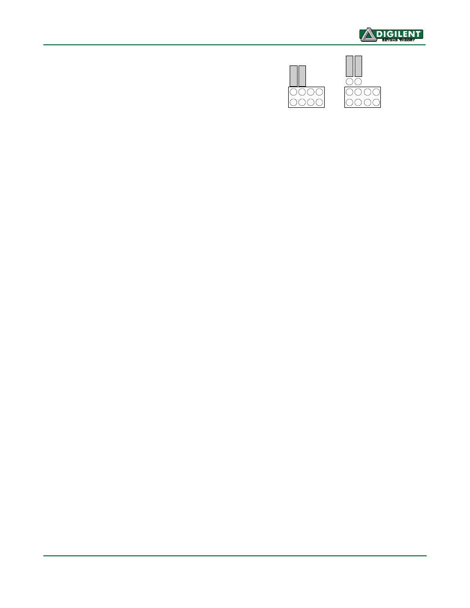
The I2C bus is an open-collector bus. Devices
on the bus actively drive the signals low. The
high state on the I2C signals is achieved by
pull-up resistors when no device is driving the
lines low. One device on the I2C bus must
provide the pull-up resistors. The I2C bus on
the I/O Explorer provides selectable pull-up
resistors that can be enabled or disabled via
jumper blocks JP4 and JP5. The pull-ups are
enabled by installing shorting blocks and are
disabled by removing the shorting blocks. The
shorting blocks are placed so that they line up
with the SCL and SDA labels on the board.
Only one device on the bus should have the
pull-ups enabled.
S
C
L
S
D
A
S
C
L
S
D
A
Pull-ups
Enabled
Pull-ups
Disabled
3
V
3
G
N
D
3
V
3
G
N
D
Jumper Settings for I2C Pull-Up Resistors
Private I2C Bus
When the I/O Explorer is operating using user
developed firmware in the primary
microcontroller, there is a private I2C bus
controlled by the primary microcontroller that is
used to talk to two peripheral devices: The
secondary microcontroller, and the Microchip
MCP4728 Digital to Analog (D/A) converter.
When running the factory firmware in the
secondary microcontroller, this microcontroller
appears as an I2C slave device on the private
bus. The command protocol for this interface is
described in the document: Digilent I/O
Explorer Slave Device Communications
Protocol available on the Digilent web site.
This document is contained in the reference
design example that illustrates the used of the
command protocol to talk to the secondary
microcontroller. The primary microcontroller
can send commands to the secondary
microcontroller for access to many of the on-
board I/O devices, such as the switches, push
buttons, LEDs, etc.
In addition to the secondary microcontroller,
there is also a Microchip MCP4728, four
channel, D/A converter on the private I2C bus.
When using the factory firmware in the primary
microcontroller, this D/A converter provides the
analog outputs accessible through the DAIO
API functions. When running user defined
firmware on the primary microcontroller, this
device is directly accessible to the user
firmware.