Dc motor controller – Digilent 410-262P-KIT User Manual
Page 3
chipKIT Motor Shield Reference Manual
www.digilentinc.com
page 3 of 8
Copyright Digilent, Inc. All rights reserved. Other product and company names mentioned may be trademarks of their respective owners.
J19: Analog Signal Pass-Through Connector
This connector passes the analog input pins on the Uno32 through the chipKIT Motor Shield.
J22: Power Pass-Through Connector
This connector passes the power connector from the Uno32 through the chipKIT Motor Shield, and
powers the chipKIT Motor Shield from the Uno32.
DC Motor Controller
The Motor Shield provides a means to control 2 independent DC motors via a DRV883 dual H-bridge
motor driver. The motor driver must be powered via J1 to operate, voltages between 2.7 and 10.8
volts are acceptable. Each ch
annel is controlled by an “enable” and “direction” signal.
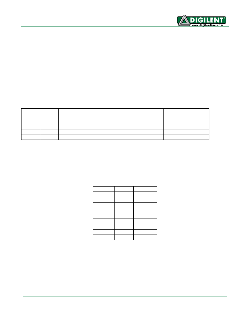
Uno32
Pin #
PIC32
Pin #
Signal
Notes
3
46
Enable1: OC1/RD0
4
59
Direction1: RF1
3/5
46/49
Enable2: OC1/RD0 or OC2/RD1
Select with JP1
4/34
59/53
Direction2: RF1 or PMRD/CN14/RD5
Select with JP2
Channel 2 can be set up for identical or independent operation from channel 1 using JP1 and JP2.
PWM levels on enable pins will regulate the speed of the motors. Logic levels on direction pins will
determine the motors rotation direction of the attached DC motors. The chipKIT Uno32 uses a
demultiplexer and pull-down resistors on the inputs to the DRV8833 H-Bridge pins to ensure that the
H-Bridge only works in fast decay mode. Table 1 lists the motor responses that result from various
input combinations.
DIR1
EN1
Result
0
0
Stop
0
1/PWM Forward
1
0
Stop
1
1/PWM Reverse
DIR2
EN2
Result
0
0
Stop
0
1/PWM Forward
1
0
Stop
1
1/PWM Reverse
Table 1: Motor Control
The DRV8833 chip provides overcurrent protection on the motor drive circuits. Each internal drive
FET is independently monitored for an overcurrent condition and will be shut down internally to protect
the chip. When an overcurrent condition is sensed the chip will shut down the FET with the fault and
then set the NFAULT pin low signaling a fault condition on the chip. The remaining FETs will continue
to operate as normal. When the fault condition is over, the chip will self-reset and return the NFAULT
logic level to logic high. (See Table 2 for connector descriptions.)