3appendix a: chipkit network shield pinout tables, 1 pins used by the ethernet interface, 2 pins used by the usb interface – Digilent 410-211P-KIT User Manual
Page 9
chipKIT™ Network Shield™ Board Reference Manual
Copyright Digilent, Inc. All rights reserved.
Other product and company names mentioned may be trademarks of their respective owners.
Page 9 of 10
2.6 32.768 KHz Oscillator
A 32.768 KHz oscillator is provided for use as a clock source for the real-time clock/calendar (RTCC) peripheral in
the PIC32MX796 microcontroller on the Max32 board. The output of this oscillator connects to pin 12 or connector
J11.
On the Max32 board, this signal connects to signal RC13, which connects to pin 73 on the PIC32 microcontroller.
This pin provides the secondary oscillator input, which can be used to clock the RTCC in the PIC32 microcontroller.
3
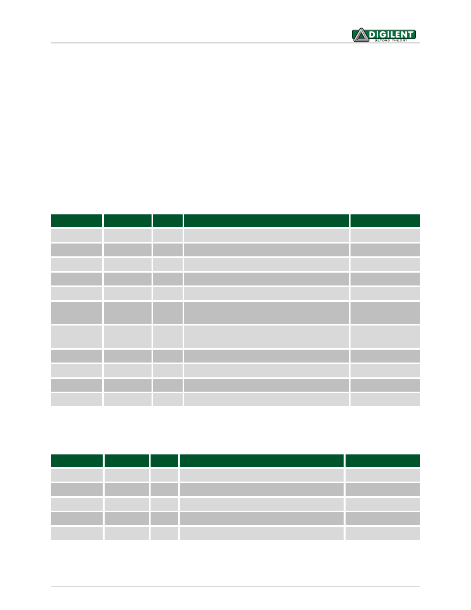
Appendix A: chipKIT Network Shield Pinout Tables
3.1 Pins Used by the Ethernet Interface
3.2 Pins Used by the USB Interface
chipKIT Pin #
PIC32 Pin #
Pin
Signal
Notes
46
88
J10-8
C1TX/ETXD0/PMD10/RF1
ETXD0
45
87
J10-9
C1RX/ETXD1/PMD11/RF0
ETXD1
47
83
J10-7
ETXEN/PMD14/CN15/RD6
ETXEN
48
68
J10-6
RTCC/EMDIO/AEMDIO/IC1/RD8
EMDIO
49
71
J10-5
EMDC/AEMDC/IC4/PMCS1/PMA14/RD11
EMDC
53
14
J10-1
ERXCLK/AERXCLK/EREFCLK/AEREFCLK/SS2A/U2BRX/
U2ACTS/PMA2/CN11/RG9
EREFCLK
43
12
J10-11
ERXDV/AERXDV/ECRSDV/AECRSDV/SCL2A/SDO2A
UATX/PMA3/CN10/RG8
ECRSDV
40
35
J10-14
AN11/ERXERR/AETXERR/PMA12/RB11
ERXERR
42
41
J10-12
AN12/ERXD0/AECRS/PMA11/RB12
ERXD0
41
42
J10-13
AN13/ERXD1/AECOL/PMA10/RB13
ERXD1
7
19
J11-15
AERXD0/INT2/RE9
NRST
chipKIT Pin #
PIC32 Pin #
Pin
Signal
Notes
27
57
J13-11
USBD+/RG2
26
56
J13-12
USBD-/RG3
25
51
J13-13
USBID/RF3
A5/59
20
J9-6
AN5/C1IN+/VBUSON/CN7/RB5
2
18
J11-5
AERXD0/INT1/RE8