1chipkit network shield hardware overview – Digilent 410-211P-KIT User Manual
Page 2
chipKIT™ Network Shield™ Board Reference Manual
Copyright Digilent, Inc. All rights reserved.
Other product and company names mentioned may be trademarks of their respective owners.
Page 2 of 10
1
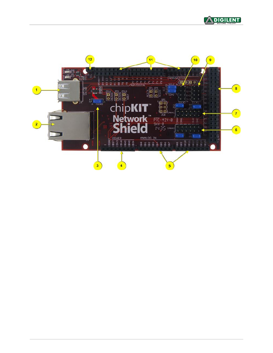
chipKIT Network Shield Hardware Overview
The Network Shield has the following hardware features:
1. USB Connectors
The connector on top of the board is a standard USB A-type receptacle. This is used when the
Max32/Network Shield combination is used as a USB host. Immediately below this connector is a USB
Micro-AB connector. This connector is used when the Max32/Network Shield is used as a USB device
or when using it as a USB OTG device.
2. Ethernet Connector with Integral Magnetics
This connector is used to connect the Max32/Network Shield to an Ethernet network.
3. JP4: USB Host Connector Selection
When the Max32/Network Shield is used as a USB host, this jumper is used to select which USB
connector is being used.
4. J17: Power Pass-Through Connector
This connector passes the power connector from the Max32 through the Network Shield and powers
the Network Shield from the Max32.
5. J9 & J12: Analog Signal Pass-Through Connectors
These connectors pass the analog input pins on the Max32 through the Network Shield.
6. CAN2 Connector
This connector provides access to the signals for CAN2.
7. CAN1 Connector
This connector provides access to the signals for CAN1.