Clocks, User i/o, Expansion connectors – Digilent 410-146P-KIT User Manual
Page 3
CoolRunner-II Starter Board Reference Manual
www.digilentinc.com
page 3 of 4
Copyright Digilent, Inc. All rights reserved. Other product and company names mentioned may be trademarks of their respective owners.
CoolRunner-II
38
Fixed Freq
Oscillator
DSC1033
Oscillator
Socket
32
Push-
buttons
Slide
Switches
CoolRunner-II
CPLD
143
94
BTN0
BTN1
SW0
SW1
3.3V
LD0
LD1
LD2
LD3
3.3V
LEDs
7-Seg
Display
AN1
AN2
AN3
AN4
124
39
69
68
66
64
130
129
128
126
25
16
23
21
20
17
83
CA
CB
CC
CD
CE
CF
CG
DP
22
VDD
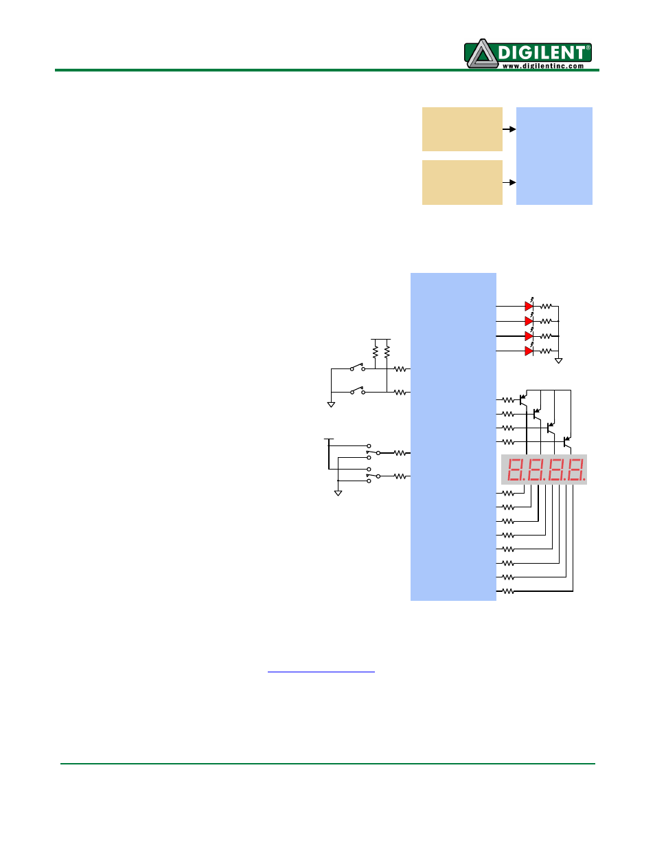
Clocks
The CoolRunner-II board includes a fixed-
frequency oscillator that produces an 8MHz
clock signal. This primary oscillator output,
labeled PCLK in the schematic, is connected to
the GCLK2 pin of the CPLD (at P38) so that it
can be routed to the internal clock divider. An
unloaded socket for a standard half-size DIP
oscillator is also provided at location IC3.
User I/O
The CoolRunner-II board provides two
pushbuttons and two slide switches for
inputs, and four red LEDs and a four-digit
LED display for outputs.
The active-low pushbuttons and slide
switches include series resistance for short-
circuit protection. The LEDs are active low,
and the seven-segment display uses
decoupled-transistor active-high common
anode signals and active-low cathodes.
Three additional LEDs indicate USB power
good (LD4), board power good (LD5), and
USB link status (LD6).
Expansion Connectors
The CoolRunner-II board provides four 12-
pin peripheral module connectors. Each
connector provides two V
DD
and GND
connections and eight unique CPLD
signals. Each connector can accommodate
a single 12-pin Pmod or two 6-pin Pmods.
Digilent makes several 6-pin Pmods that can attach to these connectors, including speaker boards, H-
bridge boards, sensor boards, etc. See
for more information.
The CoolRunner-II board also provides a 40-pin expansion connector that includes three power-
supply signals and 37 individual I/O signals.