Operation – D.A.S. Audio DSP-26 USB User Manual
Page 40
38
When using Delay Linking, it is recommended that the adjustment order is:
Driver alignment within cabinets
Cabinet alignment within clusters
Delay Alignment between clusters. In 2 channel 3 way and LCR 2 way, the default settings
include Delay Linking as well as Stereo Linking.
Using the and buttons or rotary encoder the polarity of the output signal can be invested. If the
polarity is changed on a linked Output, both Outputs will change to the same selection.
The low edge filter type can be selected from Bessel 12,24dB/Octave or Butterworth 6, 12, 18, 24 or
48dB/Octave or Linkwitz-Riley 12,24 and 48dB/Octave.
The options are displayed as:
BUT 6,
BUT12,BES12,L-R12,
BUT18,
BUT24,BES24,L-R24,
BUT48,L-R48.
This control adjusts the cut off frequency of the selected Low Frequency( high pass) Crossover. The
range is from 15Hz to 16kHz in approximately 1/6 Octave steps with 'Out' at the bottom end and
'Off' when adjusted beyond 16kHz.
11.6 Polarity
11.7 Crossover Shapes and Frequencies
Low edge filter type
Low edge filter frequency
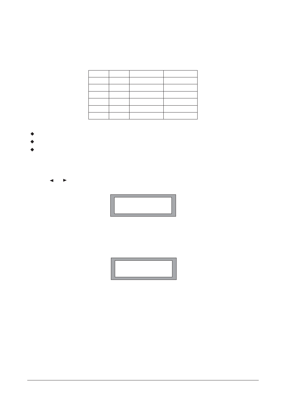
either linked channel's delay is changed, the other linked channel(s) will follow and maintain the
offset. Normally, the transducer delays are set first, then any overall delay for cluster alignment or
delay tower set-up second. The following table shows the linkable channels in each mode.
OUT 3 & 4
AUX *
POLARITY
NORMAL
OUT 5 & 6
HIGH *
LO SHAPE
L-R 24
OUTPUT
1
2
3
4
5
6
Mono
2
3
4
5
6
None
2 Channel 3 Way
3
4
5
6
None
None
3 Channel 2 Way
4
5
6
None
None
None
OPERATION
Manual del usuario/ User´s manual
DSP-26