D.A.S. Audio Variant Series Systems Guide User Manual
Page 7
0º
5º
-5º
0º
VARIANT
25
VARIANT
18
AX-V25
2
1
3
4
5
6
5
EN
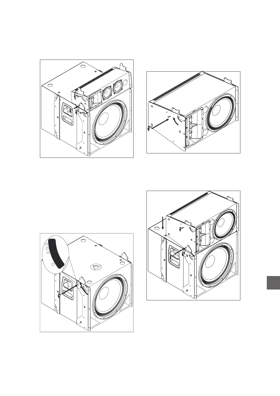
In the graph above the quick release pins have
been inserted in the center hole of the
rigging hardware, so the angle between both
systems is 0º.
variant 18A
If more cabinets are going to be stacked
repeat the process described on page 2.
The first step will be to mechanically connect
the first
unit to the
enclosure. Four safety pins, which are included in
the box, will be necessary to do so. First rotate the
connecting links (1) on the
until the
desired angle is achieved and introduce the safety
pin through the hole labeled with the desired splay
angle (2). The three available angles are 0º, 5º and
-5º. Look at the label on the
box.
variant 112A
variant 18A
variant 18A
variant18A
The rest of the boxes will be set up using the
above explained procedure for connecting rods
and safety pins ( See page 2).
In order to attach the
unit to the
subwoofer unit, introduce the connecting (5) links
on the
into the receptacles on the
. Then two safety pins (6) must be
introduced (one per side) to secure one enclosure
to the other.
variant 112A
variant 18A
variant 112A
Before attaching the first
to the
subwoofer unit, the connecting links must be
rotated (3) until the desired splay angle with the
next unit on top is reached. Once the desired
angle has been reached the safety pins will be
introduced (4) into the corresponding hole.
variant 112A
In the picture above the safety pin has been
introduced into the 0º labeled hole, while in the
picture below the safety pin has been introduced
into the +5º labeled hole.
variant S
uide
ystems G