D.A.S. Audio Variant Series Systems Guide User Manual
Page 6
4
Stacking units on the subs
0º
5º
-5º
0º
VARIANT
25
VARIANT
18
AX-V25
2
1
3
4
9
7
8
5
6
EN
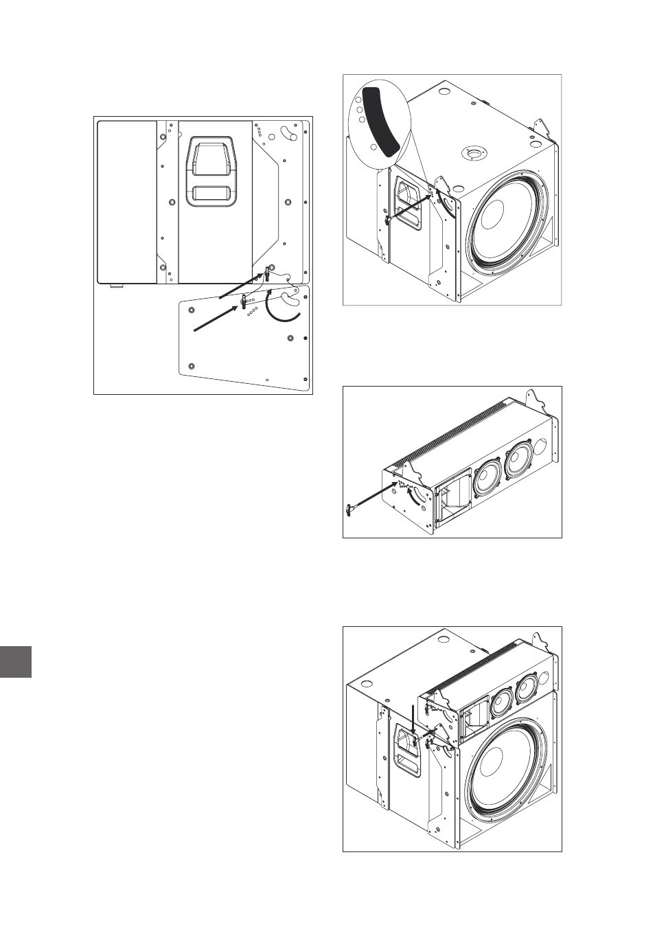
In order to attach the
unit to the
subwoofer unit, introduce the connecting (5) links
on the
into the receptacles on the
. Then two safety pins (6) must be
introduced (one per side) to secure one enclosure
to the other.
variant 25A
variant 18A
variant 25A
Before attaching the first
to the
subwoofer unit, the connecting links must be
rotated (3) until the desired splay angle with the
next unit on top is reached. Once the desired
angle has been reached the safety pins will be
introduced (4) into the corresponding hole.
variant 25A
The
units feature integral rigging
hardware which can also be used for stacking
units on top of them. The
maximum recommended number of
units in this mode is 6. The maximum number of
units to be stacked on the subs is 2.
The
splay
angles
available
between
both
enclosures are 0º, 5º and -5º.
The first step will be to mechanically connect
the first
unit to the
enclosure. Four safety pins, which are included in
the box, will be necessary to do so. First rotate the
connecting links (1) on the
until the
desired angle is achieved and introduce the safety
pin through the hole labeled with the desired splay
angle (2). The three available angles are 0º, 5º and
-5º. Look at the label on the
box.
variant 18A
variant 25A/112A
variant 25A
variant 112A
variant 25A
variant 18A
variant 18A
variant18A
The procedure in case of installing
systems is equivalent to the previous mentioned
before.
variant 112A
variant S
uide
ystems G