Crosman 1701P User Manual
Page 7
7
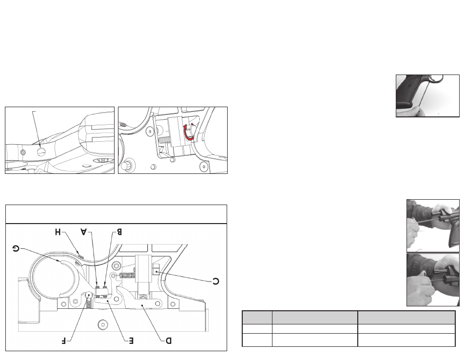
Fig 9
A. AJUST
ADOR DE LA PRIMERA ETAP
A
B. AJUST
ADOR DE LA SEGUNDA ETAP
A
C. AJUST
ADOR
DEL PESO DEL GATILLO
D. FIADOR
E. ESLABÓN
F . SEGURO
G. GATILLO
H. TORNILLO DE
EXCESO DE RECORRIDO DEL GATILLO
Resistencia del gatillo
Busque el tornillo ajustador del peso del gatillo C (Fig. 8). V
isto desde el punto de ventaja de tiro, gir
e el
tornillo en el sentido de las agujas del r
eloj (Fig. 9A) para aumentar la fuerza de resistencia del gatillo y en
sentido contrario a las agujas del reloj para r
educir la fuerza de resistencia del gatillo. Este ajuste no afecta el
enganche del fi ador
.
Fig 10A
Orifi
cio De Acceso
Fig 10B
B. Ajuste del gatillo de dos etapas
• To
rnillos ajustador
es de etapa del gatillo: Ubique el orifi cio de acceso de los tor
nillos de ajuste de etapas
debajo del bastidor de la cacha (Fig. 9B). Con una llave Allen de 0,050” para ajustar los tornillos (A) y (B),
es posible cambiar la posición y longitud de la primera y segunda etapa del movimiento del gatillo. Estos
ajustes podrían afectar el enganche del fi ador y
, por lo tanto, podrían hacer que la pistola se dispar
e al
dejarla caer o sacudirla.
• El tor
nillo (A) cambia la primera etapa. Girar el tornillo (A) en el sentido de las agujas del r
eloj aumentará
la longitud de la primera etapa y disminuirá el enganche del fi ador
. Girarlo en sentido contrario al de las
agujas del reloj disminuirá la longitud de la primera etapa y aumentará el enganche del
fi ador
.
• El tor
nillo (B) cambia la segunda etapa. Girar el tornillo (B) en el sentido de agujas del r
eloj hará que
la segunda etapa ocurra más rápido; girarlo en sentido contrario al de las agujas del reloj hará que la
segunda etapa ocurra después.
• El ajuste de los tor
nillos (A) y (B) debe hacerse en conjunta armonía, ya que trabajan unidos para crear el
perfi l del gatillo. Empiece lentamente para entender lo que hace cada ajuste y su r
elación con el otro.
• Después de ajustar el gatillo, siempr
e verifi que que el gatillo y el segur
o estén funcionando correctamente.
Si no está seguro de que el gatillo o el segur
o funcionan correctamente, lleve su arma a un armer
o experi-
mentado.
• Vuelva a colocar la cacha y el tor
nillo de la cacha.
7
• For creating a single stage trigger, adjust screw (A) clockwise until the desired Sear engagement is
attained. Adjusting screw (A) in this manner will eliminate engagement of screw (B) and will yield the
lightest possible single stage trigger pull. Screw (B) can also be utilized to create single stage trigger by
turning in clockwise until the desired Sear engagement is attained. It is advised to also turn Screw (A) out
counter-clockwise a few turns to ensure it is no longer engaged at any point. Which screw is utilized to
create the single stage trigger depends on the preference of the individual.
• After adjusting your trigger, always check that the trigger and safety are functioning properly. If you are not
sure if the trigger or safety is operating properly, take your gun to an experienced gunsmith.
• Replace the Grip and Grip screw.
D. Maintaining the Marauder Pistol Trigger
• The Marauder pistol trigger is assembled with a moly graphite EP grease that should last for years. In the
event your trigger becomes contaminated with debris and is not functioning properly, contact a qualifi ed
gunsmith to examine for repair or necessary maintenance.
E. Adjusting the Trigger Over-travel
• To ensure crisp, consistent action of the trigger, a set screw has been
incorporated into the trigger guard to allow each shooter to set the
trigger over-travel to their preference. Removing the screw will give the
most over travel, tightening the screw all the way in will stop the trigger.
Shooters will fi nd their preference somewhere in between.
• Make sure the air pistol is unloaded (section 4B) and de-gassed (section 3D)
• Turn the set screw (H) as shown in Figure 8, all the way in with a hex wrench.
(not included)
• Cock the bolt by pushing the bolt handle up and pulling it all the way
back. Close the bolt and push the bolt handle down to lock.
• Point the air pistol in a SAFE DIRECTION, take “OFF SAFE” (section 2B) and pull the trigger. If the pistol
does not fi re, turn the set screw counter clockwise in ½ turn increments until it fi res.
IMPORTANT! Turn an additional ½ turn counter clockwise. This is important to ensure proper operation of
the trigger.
• Put the air pistol “ON SAFE”.
10. Adjusting for Various Fill Pressures and Velocities
• Proper adjustment of the 1701P requires use of a chronograph.
• The 1701P has been factory set for a fi ll pressure of
2900 psi and velocity of approximately 450 fps.
These settings will suit most target uses and will yield a long usable shot string. If you, as the owner, wish
to alter the factory settings you should do so only after reading the following instructions carefully.
• The 1701P is designed to be tuned to work at various fi ll pressures from 2500 psi (172 bar) up to 3000
psi (207 bar). This is done by adjustment of the hammer spring preload and hammer stroke length. In
either case the adjustment changes the amount of energy the hammer generates when striking the valve.
Higher fi ll pressures require more hammer energy while lower fi ll pressures require less hammer energy.
Higher fi ll pressures will typically yield more usable shots from a given charge. It is advised to always
record your settings when tuning your airgun.
• The 1701P can be adjusted to achieve various velocities using the same procedures described herein.
This would mainly be done to compensate for heavier pellets IE 10.5 grain vs. 7.9 grain.
A. Hammer Spring Preload Adjuster
The hammer spring preload adjuster may be accessed through the rear plug on
the reservoir tube with a 3/16” Allen wrench as shown in fi gure 11. To increase
hammer energy turn the preload adjuster clockwise up to 7 revolutions. This
would be the case when starting from all the way back counterclockwise.
NOTE: More revolutions will simply cause the adjuster to spin but will not yield any
higher force. Increasing the preload will be required to facilitate use of higher fi ll
pressure.
To lessen hammer energy turn the adjuster counterclockwise. It is advised to
always record your settings when tuning your airgun.
B. Stroke Adjustment
The striker can be accessed through the hammer spring preload adjuster using a
1/8” Allen wrench (fi g 12). Turning the striker clockwise will shorten the hammer
stroke and turning counter clockwise will lengthen the stroke. A long stroke length
will yield higher hammer energy while a short stroke length will yield lower hammer
energy. The striker can be adjusted inward by up to 12 revolutions though this
many turns would never be necessary.
• A starting point for low fi ll pressures would start with a low hammer spring
preload tension and a shorter hammer stroke.
• A starting point for higher fi ll pressures will require more hammer spring
preload tension and a longer hammer stroke. Refer to the chart below for sug-
gested combinations of these adjustments based on fi ll pressure.
Fill
Pressure
Hammer Spring Preload
Hammer Stroke
Higher
Increase, turn adjuster in (Clockwise)
Increase. Turn Striker out (Counter Clockwise)
Lower
Decrease, turn Adjuster out (Counter
Clockwise)
Decrease. Turn Striker in (Clockwise)
Fig 11
Fig. 12
Fig. 13
Fig. 13