Advertencia – Crosman BP2263 User Manual
Page 7
WARNING:
Adjustment of trigger screw (B) could inhibit proper function of the safety
lever (F). Thus, always check for full engagement and smooth function of the safety lever
upon completion of any changes to the trigger screw. If you are not sure if the safety is en-
gaging and operating properly, take your gun to an experienced gunsmith.
WARNING:
Adjustment to the trigger assembly could allow this airgun to fire if dropped
or jarred, with or without the safety engaged.
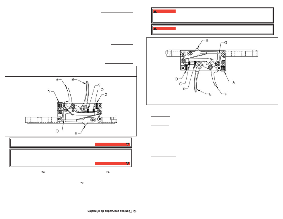
A. TRIGGER WEIGHT ADJUSTER B. FIRST STAGE ADJUSTER C. SECOND STAGE ADJUSTER
D. TRIGGER POSITION E. TRIGGER F. SAFETY LEVER G. LINK H. SEAR
Trigger Pull
•
Using a 1/8” Allen wrench turn the adjuster screw (A) clockwise to increase trigger pull
weight and counterclockwise to decrease trigger pull weight. This adjustment will not affect
sear engagement.
Trigger Position
•
Using a .050” Allen wrench the trigger position at rest can be adjusted. Turn screw (D)
clockwise to move the trigger back and counter clockwise to move the trigger forward. This adjustment
could affect sear engagement, and therefore could allow the gun to fire when dropped or jarred.
Trigger Stages
•
Using a .050” Allen wrench for adjustment of screws (B) and (C), changes can be made
to the position and length of first and second stages of the trigger motion. These adjustments could
affect sear engagement, and therefore could allow the gun to fire when dropped or jarred.
Screw (B) changes the first stage. Turning screw (B) clockwise will increase the length of the first
•
stage and decrease the sear engagement. Turning counter clockwise will decrease the length of
the first stage and increase the sear engagement.
Screw (C) changes the second stage. Turning screw (C) clockwise will cause the second stage to
•
occur sooner while turning counterclockwise will cause the second stage to occur later.
Adjustment of screws (B) and (C) should be done in harmony with each other as they work
•
together to create the trigger’s profile. Start slowly to understand what each adjustment does and
its relationship to the other.
Trigger Maintenance
•
The trigger is assembled with a moly graphite EP grease that should last for years.
In the event your trigger becomes contaminated with debris and is not functioning properly, contact a
qualified gunsmith to examine for repair or maintenance.
After adjusting your trigger, always check that the trigger and safety are functioning properly. If you are
•
not sure if the trigger or safety is operating properly, take your gun to an experienced gunsmith.
Re-insert the action into the stock, and replace and tighten the stock screw.
•
B. Adjusting for Various Fill Pressures
The Marauder is designed to be tuned to work at various fill pressures from 2000 psi (138 bar) up
•
to 3000 psi (207 bar). This is done by adjustment of the hammer spring preload and hammer stroke
length. In either case the adjustment changes the amount of energy the hammer generates when strik-
ing the valve. Higher fill pressures require more hammer energy while lower fill pressures require less
hammer energy.
It is advised to always record your settings when tuning your airgun.
(See Page 10)
The Marauder has been factory set to an efficient fill pressure that will suit most hunting and target
•
uses. If you, as the owner, wish to alter the factory settings you should do so only after reading the fol-
lowing instructions carefully.
Hammer Spring Pre-load adjuster
•
Put the air rifle “ON SAFE” (see section 2A), remove the clip and keep the airgun pointed in a SAFE
•
DIRECTION. Remember that the airgun is pressurized and make only the adjustments identified
in this manual.
A. A
juste del gatillo
El conjunto
del gatillo
de
l Mar
aud
er s
e puede ajustar y personaliza
r, pe
ro a
menos que usted tenga exper
i-
encia en la
re
alizaci
ón de ta
les
ajustes
, C
rosman
recomienda que estos ajustes a los valo
res de fábrica sea
n
reali
zados sól
o por un arme
ro
califi
cado después de leer todas las instrucciones. Ajustar el conjunto del g
a-
tillo puede dar co
mo
result
ado una poca
resistencia del gatillo, menor enganche del fiador que podría causa
r
que se disp
are
al caerse
o sa
cud
irse,
o que el segu
ro no funcione. Haga ún
icamente los ajustes identificado
s
en este manual
.
NOTA
: estas func
iones d
e ajuste
son
par
a tirado
res avanzados. La mayoría de los tirado
res pueden usar l
a
configuración propo
rcionad
a dur
ant
e la fabricación del rifle, y no deberían tener que hacer modificaciones
.
• E
l gatill
o d
e calida
d d
e competenci
a d
e s
u
de
ai
re
de
diábolos
es
una
unidad
de
dos
etapas
totalmente
ajust-
able
. Se h
a a
justado de fábrica a
un
est
ado eficiente que será ade
cua
do para la may
oría
de los usos
de cacería
y
tiro al
blan
co.
Si usted, como
pr
opiet
ario
, desea
alt
erar l
os
ajustes de fábrica
, debe hacerlo ún
icamente despué
s
de leer
cuidadosamente l
as
sigu
ientes instruc
ciones
.
• Activ
e e
l segu
ro
del
de
ai
re
(“ON
SAFE”)
, quit
e e
l cargado
r y
manteng
a e
l
apuntad
o e
n un
a DIRECCIÓ
N
SEGU
RA. Despresurice el rifle
de
ai
re
(ve
a la sección
4)
El ajuste del tornillo del gatillo (B) podría impedir la función
adecuada de la palanca del seguro (F). Por tanto, compruebe siempr
e el enganche completo
y el funcionamiento suave de la palanca del seguro al finalizar cualquier cambio en estos
tornillos de ajuste. Si no está segur
o de que el seguro se esté enganchando y funcionando
correctamente, lleve su arma a un armer
o experimentado.
ADVERTENCIA:
Los ajustes al conjunto del gatillo podrían hacer que este rifle de
aire se dispar
e al caer o al sacudirse, con o sin el seguro puesto.
ADVERTENCIA:
A. AJ
US
TADOR
DEL PESO DEL
GAT
ILLO
B. AJUS
TADOR DE LA PRIMERA
ET
APA
C. A
JUS
TADO
R
DE LA SEGUND
A ETA
PA
D. POSICIÓN
DEL G
ATILLO
E.G
ATILLO
F . P
ALANC
A DEL SEGU
RO
G.
ESLABÓN
H. FIA
DO
R
•
Resistencia de
l g
atillo
Con un
a llave
All
en de
1/
8”
gire
el to
rnill
o de ajuste (A
) en
el sentido d
e las
mane
cilla
s
del r
eloj par
a a
umentar
la
fuerza de re
sistencia del
gatillo
y
en sentido contrario
al d
e las
manecillas del
reloj par
a
disminuir la fuerza de
res
ist
enc
ia del
gatill
o. Este
ajuste
no
afectará
el enganche
del fiad
or.
•
Posici
ón
del gatillo
Con un
a llave
All
en de
.0
50”
se puede ajustar la p
osición
del gatillo en des
canso
. G
ire e
l
tornill
o (D
) en el sentido de l
as manec
illa
s del
reloj para m
ove
r el gatillo haci
a atr
ás y
en
se
ntido contr
ario
a las
manecillas del
reloj
pa
ra m
overlo h
aci
a delant
e. Este ajuste
podría afe
ctar
el eng
anche del fiado
r, y por t
ant
o
podría hacer que el
rifle
se d
ispa
re al
ca
erse
o sacudirse
.
•
Etapas del gati
llo
Con una
lla
ve All
en de
.0
50”
para los
to
rnillos
(B)
y (C
), se pueden hacer cambi
os a l
a
posición y
longitud de la prim
era
y s
egunda etapas
del
movimiento d
el g
atillo. Est
os
ajustes podrían afect
ar e
l
enganch
e de
l fiado
r, y
por t
anto
podrían hacer que el
rifle se disp
are al
caerse
o s
acudirse
.
• E
l to
rnill
o (B
) cambi
a la
primer
a etapa
. Gira
r e
l to
rnill
o (B
) e
n e
l sentid
o d
e la
s manecilla
s de
l relo
j aumentar
á
la longitud de la primer
a etapa
y
disminuirá el en
ganche d
el fiad
or.
Girarl
o en sentido contrari
o a
l de las m
an-
eci
llas de
l re
loj disminuirá la longitud
de la
pri
mera
et
apa
y
aum
ent
ará
el engan
che
del fiado
r.
• E
l to
rnill
o (C
) cambi
a la
segund
a etapa
. Gira
r e
l to
rnill
o (C
) e
n e
l sentid
o d
e la
s manecilla
s de
l relo
j har
á qu
e la
segunda etapa
ocurra más
rá
pido,
mientr
as que
girarlo en
sentid
o contrario al de
las man
eci
llas d
el r
eloj
har
á
que la se
gunda et
apa
ocurra después
.
• E
l ajust
e d
e lo
s to
rnillo
s (B
) y
(C
) deb
e hacers
e e
n armoní
a un
o co
n ot
ro,
ya
qu
e trabaja
n unido
s par
a c
rea
r
el perfil de
l gatill
o. Empiece l
ent
am
ente
para entender lo que hace cada
ajuste
y l
a relación que tiene con e
l
otro
.
• Manten
im
iento
del gatill
o El
gatil
lo
est
á e
nsamblado
co
n una gras
a EP de
m
oly
grafito qu
e de
be durar
añ
os.
En
cas
o d
e que
el gatillo
se c
onta
mine
con
de
sechos
y no
est
é fun
cion
ando
ad
ecuad
amente
, co
muníquese
con u
n
armero
cal
ificad
o p
ara
que lo
exam
ine
y
haga
las
reparac
ione
s o
manten
imiento
ne
cesari
os.
7
7