COMP Cams 5491 Sprint Car Front Drive Kit for LS Engines User Manual
Page 6
COMP Cams
®
3406 Democrat Rd.
Memphis, TN 38118
Phone: 901.795.2400
Part #COMP4-158
Revised 8/10/12
Toll Free: 1.800.999.0853
www.compcams.com
Step 7: Proper backlash is 0.010-.015" of clearance between each gear. An easy way to attain this
setting is to run a stack of newspaper into the gears that is two sheets thick, then force the gears
together and tighten the two mounting plate bolts to 27 ft-lbs.
Step 8: Mount the oil pump/magneto adapter [15] and cam trigger wheel [10] (if using a cam sensor in
your set up.) Do this by locating the adapter onto the shoulder on the front of the cam gear. Install the
cam trigger wheel over top of the adapter so that you can see the two 1/8" holes in the cam gear
through the two holes along the perimeter of the trigger wheel. Then attach the adapter and trigger
wheel using the M6x16mm low profile socket head cap screws [31]. Torque to 10 ft-lbs.
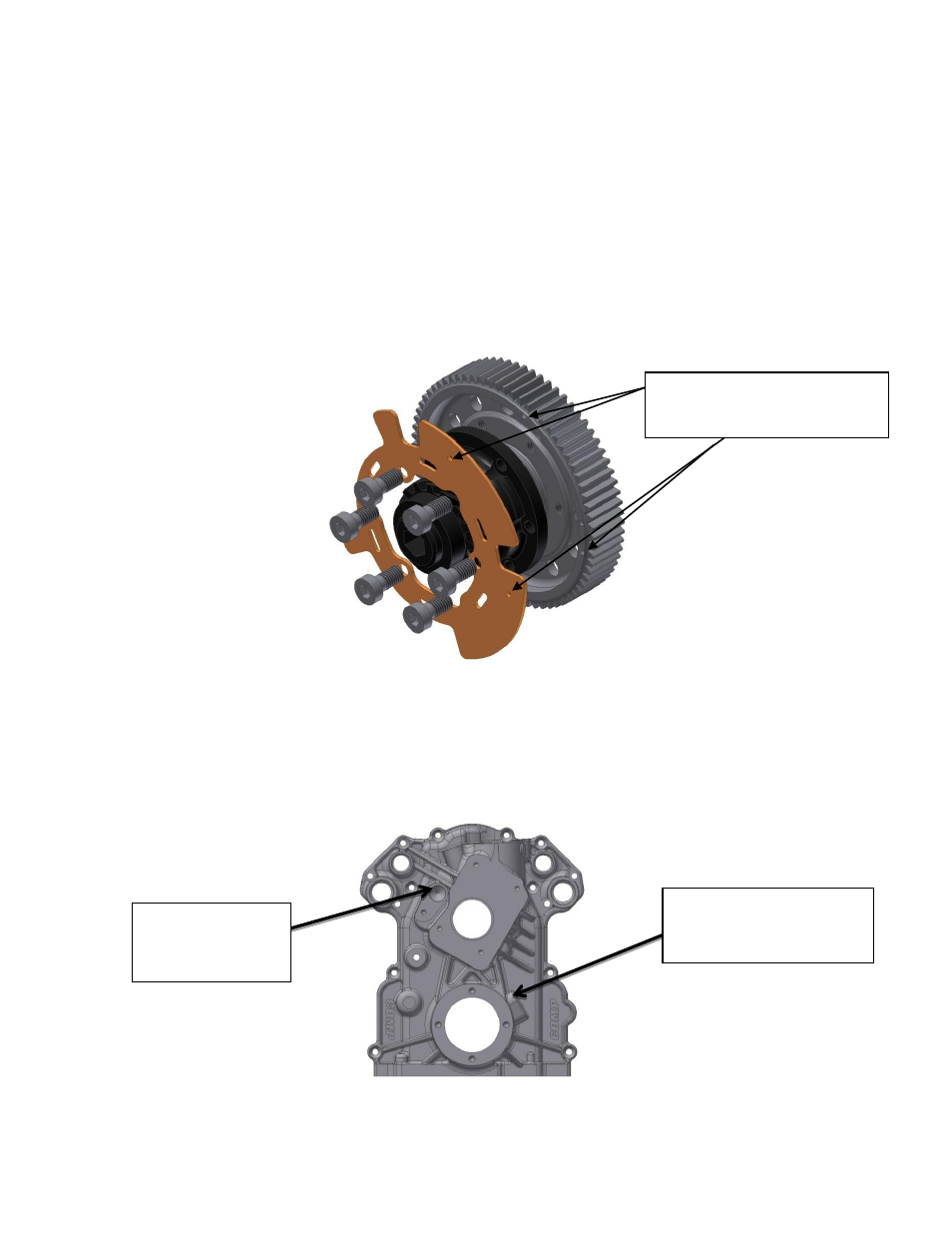
Step 9: At this point, if you plan to use an integrated cam and/or crank sensor, drill out the appropriate
hole(s) in the cover. The cam sensor hole should be drilled to 20mm and the crank sensor hole to 5/8".
Figure 3: Sensor Holes
Cam Sensor Hole
Location. Drill to
20mm.
Crank Sensor Hole
Location. Drill to 5/8".
Hole in trigger wheel must
align with hole in cam gear.