Clippasafe 118/1 Extendable, Dual Fix Push to Lock Gate User Manual
Page 9
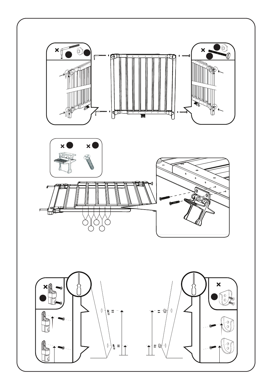
4
89 mm
756 mm
2
2
88 mm
755 mm
J
C
5. Mark the positions for the hinges ‘J’ on the wall surface you want the gate to hinge from.
The top hole for the lower hinge should be 88mm from the floor. The top hole for the upper
hinge should be 755mm from the floor. On the opposite wall surface mark the positions for the
wall cups ‘C’. The top hole for the lower wall cup should be 89mm from the floor and the top
hole for the upper wall cup should be 756mm from the floor.
3. Insert the 2 hinge bars ‘I’ with 2 nuts ‘E’ into the holes provided on one side of the gate.
Then insert 2 spindles ‘D’ with 2 nuts ‘E’ into the holes provided on the other side of the gate.
Make sure that both hinge bars and spindles are all inserted the same distance into the gate.
2
2
I
E
D
E
4. Attach the pedal ‘F’ to the centre of the gate using the two screws ‘G’ provided. Use the
correct holes, depending on the width of the opening,
as in Step 1.
1
2
F
G
X5
X4
X3
X2
X1