360°x6 – Clippasafe 118/1 Extendable, Dual Fix Push to Lock Gate User Manual
Page 10
Apply downward pressure to the gate from the middle of the top bar. Ensure that when closed,
the distance between the gate and the wall on both sides is not less than 21mm and not
greater than 63mm.
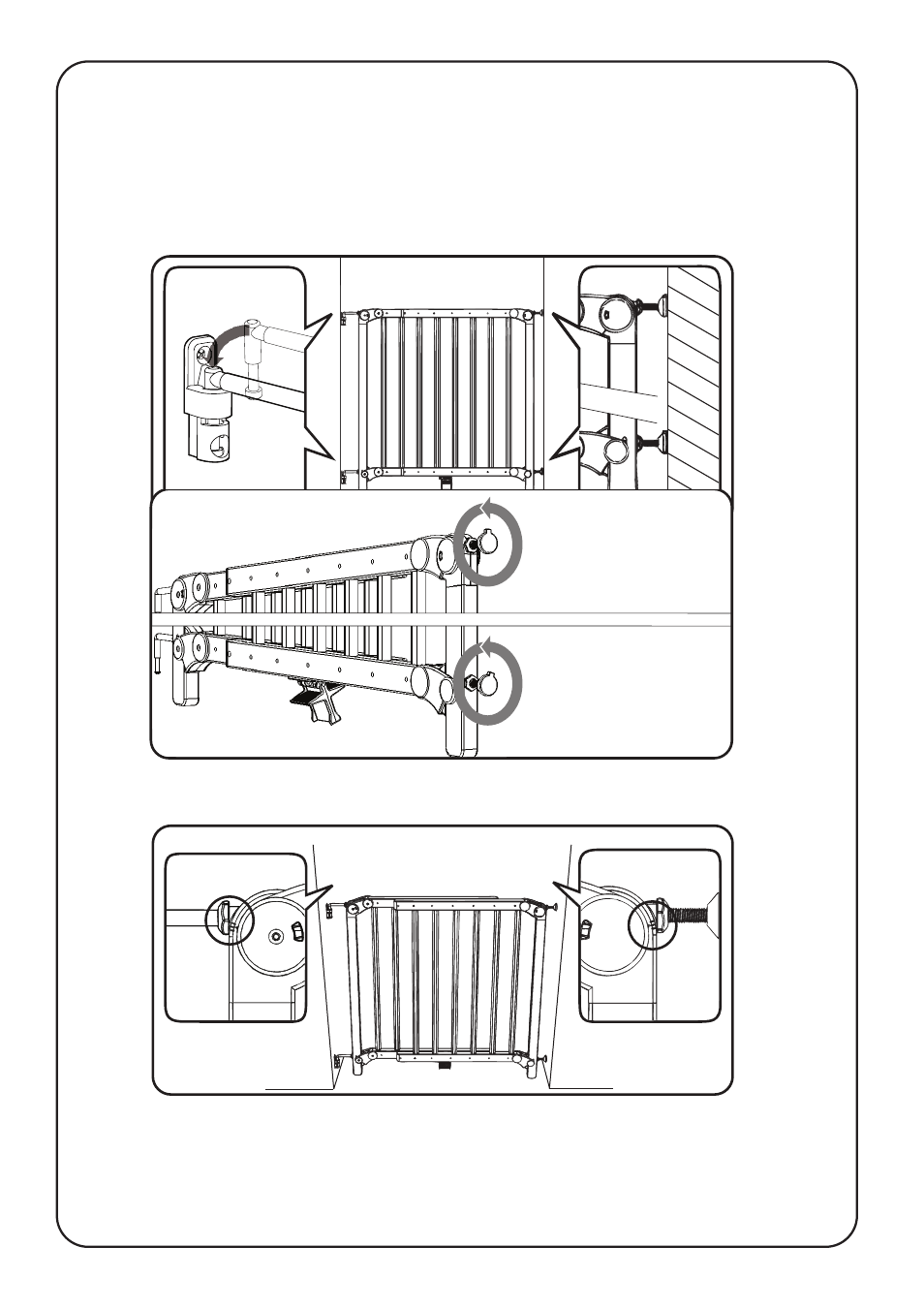
IMPORTANT ! Make sure that when the gate is closed, the pressure indicators on the top of
the gate are displaying a green window and the pedal underneath the gate can move freely.
If the pedal cannot move freely, turn the spindles on one side another full turn counter-clockwise.
7. Place the gate into the opening . Before applying any pressure, check that the pressure
indicators on the top corners of the gate are between the two markers.
Fix the hinges ‘J’ and wall-cups ‘C’ to the wall using appropriate fixings depending on the wall
surface: Wood screws for wooden surfaces, appropriate wall plugs and screws for concrete /
brick / plaster walls, or metal screws for metal surfaces. These screws are not provided.
Use Size 6 (3.5mm diameter) flat head counter sunk screws of minimum length 25mm.
6. Place the gate into the opening, making sure that the pedal touches the floor. Adjust the
hinge bars and spindles equally on the corners of the gate so that they are each touching the
wall. Remove the gate from the opening and turn both spindles six times counter-clockwise.
360°x6
360°x6