Step 1, Step 2, Figure 2-2 removing a wic or vic slot cover – Cisco 1751 User Manual
Page 34: See m anu al b efor e in stal latio n, Chapter 2 installation installing wics and vics
Chapter 2
Installation
Installing WICs and VICs
2-6
Cisco 1751 Router Hardware Installation Guide
78-11258-04
Warning
Do not work on the system or connect or disconnect cables during periods of
lightning activity.
Caution
Do not connect a WAN, telephone or fax cable to the card until you have
completed the installation procedure.
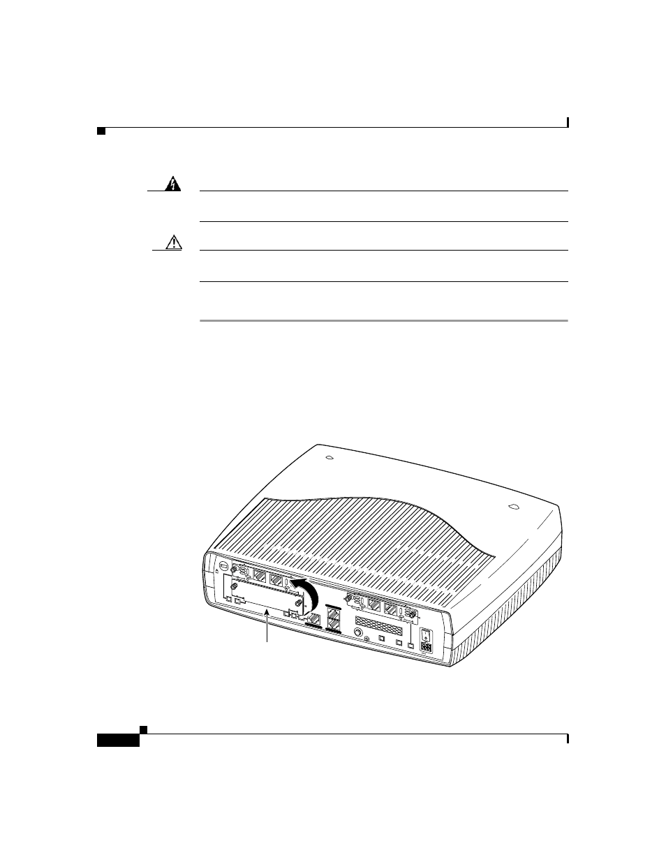
Follow these steps to remove and insert a card in the router:
Step 1
Make sure the router is turned off and is disconnected from the power supply.
Step 2
Loosen the thumbscrews on the WIC or VIC slot cover on the rear panel, as shown
in
You should be able to loosen the screws using your fingers; however, if the screws
are very tight, you might need to use a Phillips screwdriver.
Figure 2-2
Removing a WIC or VIC Slot Cover
46564
Interface card slot cover
+5, +12, -12
VDC
CONSOLE
AUX
Model Cisco 1751
10/100 ETHERNET
SEE M
ANU
AL B
EFOR
E IN
STAL
LATIO
N
VIC
2FXO
PVDM O
K
MOD O
K
SLOT 1
SLOT 2
OK
FDX
SLOT 0
OK
SLOT 1
OK
100
LINK
THIS S
LOT
ACCEP
TS
ONLY V
OICE
INTERF
ACE
CARDS
SLOT 2
SLOT 0
1
IN USE
0
IN USE
SEE M
ANU
AL B
EFOR
E IN
STAL
LATIO
N
VIC
2FXS
1
IN USE
0
IN USE