Carl Goldberg GPMA1993 Skylark 70 Sport ARF User Manual
Page 14
14
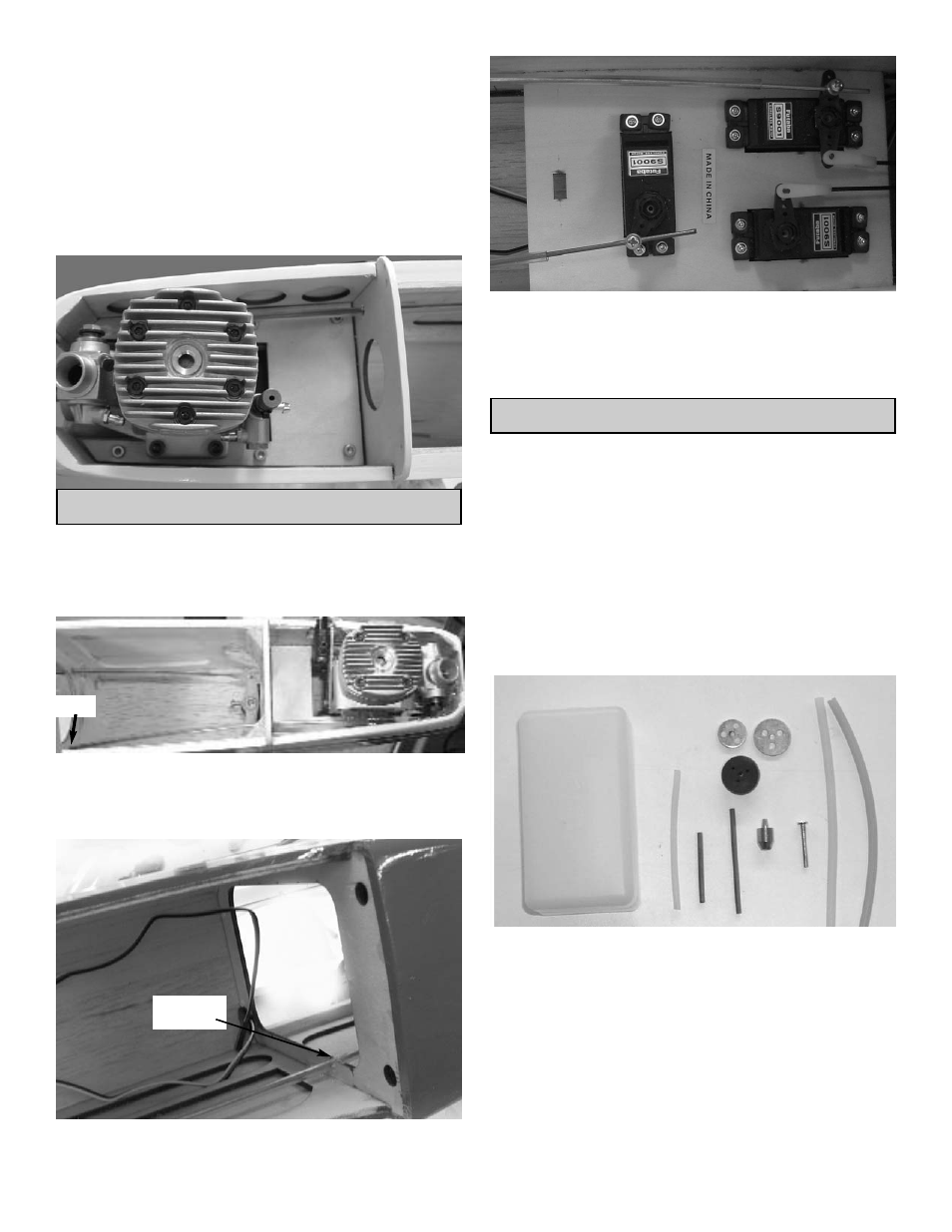
7.
Install the T-nuts on the bottom side of the
mount.
Bolt the engine to the mount plate.
8.
Re-install the engine and plate into the fuse.
Mark the location of the six holes you drilled in
the plate on the beams.
Drill a 3/32” hole at the marks and use six
#6x3/4” screws to secure the plate.
2.
Slide the throttle pushrod tubing into the hole
in the firewall that you drilled earlier.
Attach the clevis to the engine throttle arm.
Hole
3.
Make a notch in the bulkhead for the nylon
tube to fit into.
THROTTLE PUSH ROD INSTALLATION
1.
C
OLLECT THE FOLLOWING PARTS
(1) 1.5
MM X
40
CM
(1)
NYLON TUBE
(1)
NYLON CLEVIS
.
notch
4.
Place the EZ connector on the throttle servo
arm just as you did earlier.
Slide the throttle pushrod through the EZ con-
nector and adjust as necessary.
1.
G
ATHER THE FOLLOWING ITEMS
(1)
FUEL TANK
(1)
RUBBER TANK STOPPER
(1)
CLUNK
(1) 3
MM X
25
MM SCREW
(1)
CAP WASHER LARGE
(1)
CAP WASHER SMALL
(1) 3
MM X
40
MM BRASS TUBE
(1) 3
MM X
60
MM BRASS TUBE
(1)
SILICONE TUBE
4
MM X
80
MM
(2)
SILICONE TUBE
5
MM X
165
MM
FUEL TANK ASSEMBLY