Carl Goldberg GPMA1993 Skylark 70 Sport ARF User Manual
Page 12
12
5
.
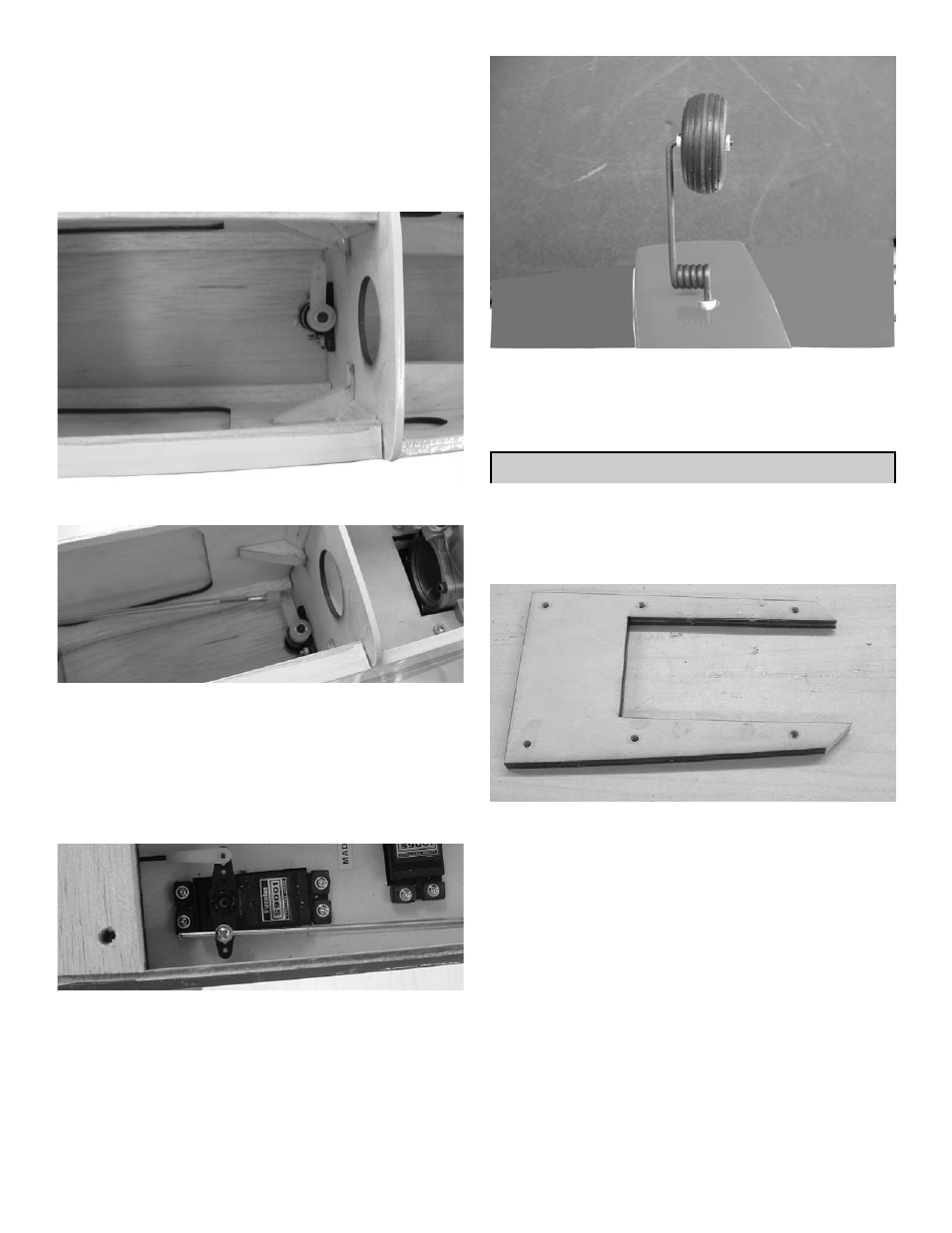
Slide the steering arm on the top of the nose
gear strut.
There is a flat spot on the front side of the strut
rotate the strut till it is pointing backwards and
the set screw aligns with the flat spot
Tighten the screw in the steering arm as
shown above.
7
.
slide the push rod tube through the former and
into the fuel tank compartment.
Insert the 1.5mm wire into the tube and con-
nect the clevis to the arm.
6.
Rotate the nose gear around into position.
8.
Slide the nose gear wire into the hole in the
EZ connector and center the servo arm and
the nose gear wheel.
When satisfied, tighten the set screw on the
EZ connector.
ENGINE INSTALLATION
1.
C
OLLECT THE FOLLOWING PARTS
(1)
ENGINE
(6) #6
X
3/4
SHEET METAL SCREWS
(3)
MOTOR MOUNT PLATES
(1)
SPINNER
(3”
NOT INCLUDED
)
9.
Install the nose gear with a wheel collar on
each side.
2.
Locate the 1/4” motor mounting plate. This is
designed as a break away plate. Drill six 9/64”
holes in the approximate position shown. The
location is not critical, just make sure not to
put them where the engine will sit.