Rudder servo installation – Carl Goldberg GBGA1091 User Manual
Page 10
10
6.
Repeat for the other three horns.
7.
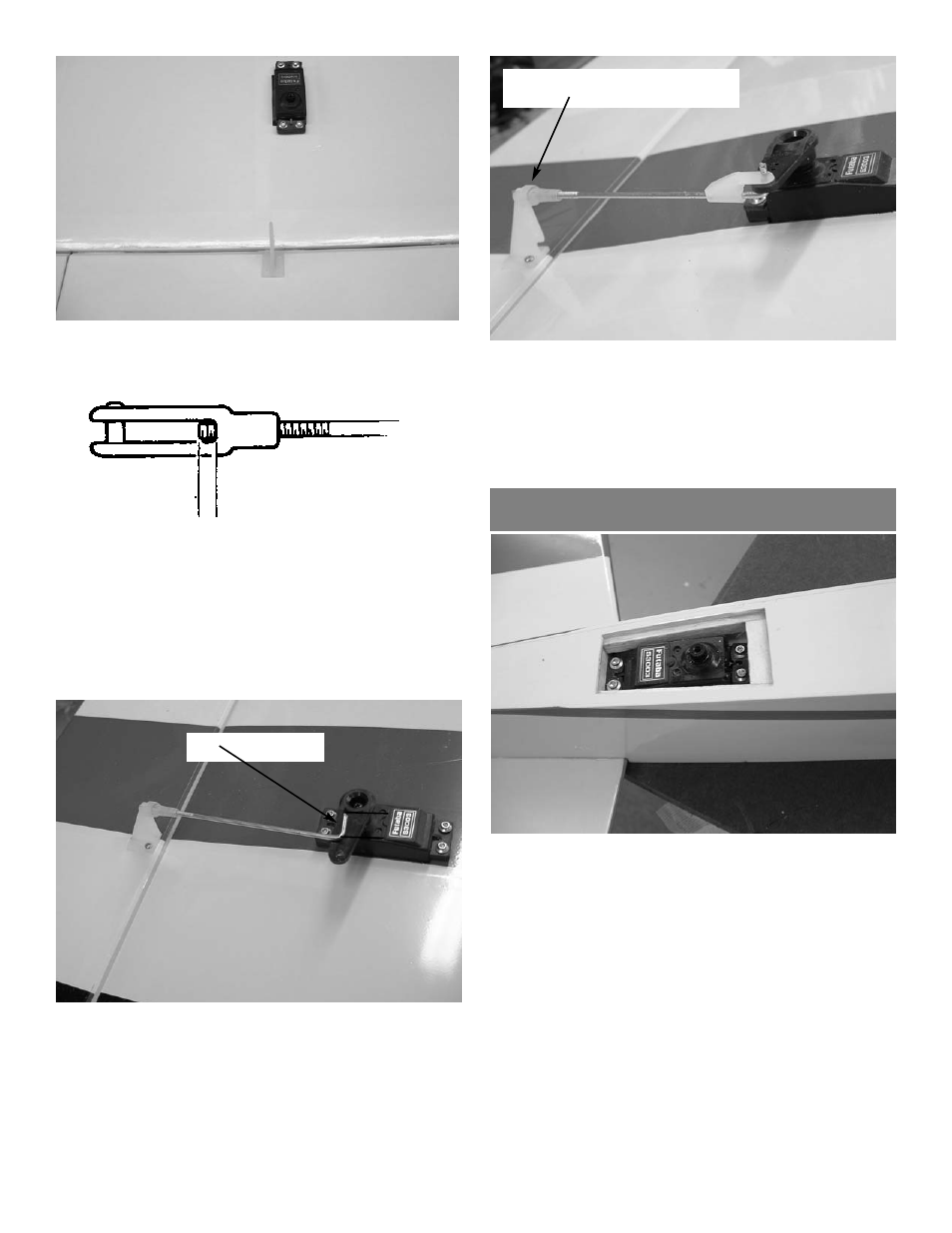
Locate the four 2-56 x 6” pushrods and install
the nylon snap link on the end. Thread the rod
into the snap link until 1/16” extends into the
opening. Slide the silicone tubing clevis keep-
er over the snap link.(silicone tubing 1/4” long)
1/16”
8.
Install the snap link on the control horn. With
the aileron servo centered and the aileron
level, mark the point where the pushrod cross-
es the control arm on the servo and make a 90
degree bend. But the bend off at 3/8”. To get
full potential out of the plane you will need a
heavy duty servo arm 1 to 1-1/4” long.
3/8”
9.
Install the pushrod in the servo output arm
and retain with the nylon swing in keeper.
Push the silicone clevis keeper down to the
control horn.
10.
Repeat for the other aileron and both flaps.
silicone tubing keeper
Rudder Servo Installation
1.
Mount the rudder servo in the opening provid-
ed on the bottom of the fuselage just in front
of the stab. You will need a 1” extension on
the servo lead. Be sure to tape the plug
together so it does not come loose.