3 camera shroud installation – Costar CDC2500MI User Manual
Page 12
11
2.3 Camera Shroud installation.
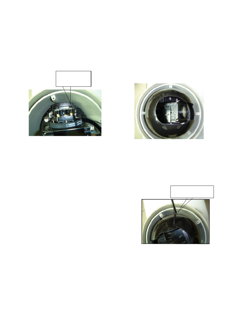
Figure 10. Illustrates the location of the screw holes for the camera shroud. (4 x M3)
Figure 11. Illustrates the camera shroud in position over the camera module
Fig. 10 Fig. 11
Step 1
: Position the open end of the camera shroud towards the camera lens as illustrated on
Figure 11. Align the 4 holes of the shroud with the 4 holes on the motor support of the
dome as illustrated in Figure 12.
Step 2
: Utilizing the supplied (4) four M3*5 screws
securely tighten the camera shroud in place,
as illustrated in Figure 12.
Fig.12
Screw holes of
camera shroud
Tighten the screws
This manual is related to the following products: