Figure 2.7, Installation – AERCO KC1000 Water Heater July 2011 User Manual
Page 13
INSTALLATION
2-5
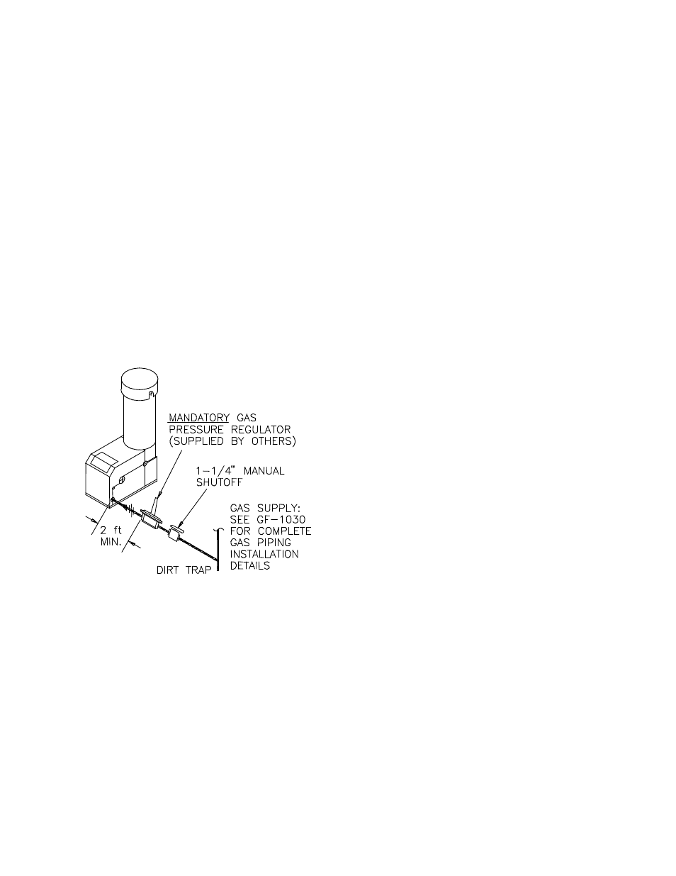
The location of the 1-1/4" inlet gas connection
on the right side of the unit is shown in Figure
2.7.
All pipe should be de-burred and internally
cleared of any scale or iron chips before
installation. No flexible connectors or non-
approved gas fittings should be installed. Piping
should be supported from floor or walls only and
must not be secured to the unit.
A suitable piping compound approved for use
with gas should be used sparingly. Any excess
must be wiped off to prevent clogging of
components.
To avoid damage to the unit when pressure
testing gas piping, isolate the unit from the gas
supply piping. At no time should there be more
than 1 psig maximum to the unit. Bubble test all
external piping thoroughly for leaks using a soap
and water solution or suitable equivalent. The
gas piping must meet all applicable codes.
Figure 2.7
Gas Supply Regulator and Manual Shut -
Off Valve Location
2.4.1 GAS SUPPLY PRESSURE
REGULATOR
A mandatory external, in-line, supply gas
regulator (supplied by others) must be installed
upstream of each KC1000 and positioned as
shown in Figure 2.7. Union connections should
be placed in the proper locations to allow
maintenance of the regulator if required. The
regulator must be capable of providing the
required gas pressures for natural gas and
propane units as described in the paragraphs
which follow.
Natural Gas:
The maximum static inlet pressure to the unit
must be no more than 14” W.C. Minimum gas
pressure is 8.8” W.C. for FM gas trains and
9.2” W.C. for IRI gas trains when the unit is
firing at maximum input. Gas pressure should
not exceed 11.5” W.C. at any time when firing.
Proper sizing of the gas supply regulator in
delivering the correct gas flow and outlet
pressure is mandatory. The gas supply
pressure regulator must maintain the gas
pressure at a regulated 8.8” W.C. minimum
for FM gas trains and 9.2” W.C. for IRI gas
trains at maximum BTU input (970,000
BTU/HR) for natural gas installations. The
supply gas regulator must be of sufficient
capacity volume, (1000 cfh), for the unit and
should have no more than 1" droop from
minimum to full fire.
Propane:
The maximum static inlet pressure to the unit
must be no more than 14” W.C. Minimum gas
pressure is 7.7” W.C. for FM gas trains and
8.1” W.C. for IRI gas trains when the unit is
firing at maximum input. Gas pressure should
not exceed 11.5” W.C. at any time when firing.
Proper sizing of the gas supply regulator in
delivering the correct gas flow and outlet
pressure is mandatory. The gas supply
pressure regulator must maintain the gas
pressure at a regulated 7.7” W.C. minimum
for FM gas trains and 8.1” W.C. for IRI gas
trains at maximum BTU input (1,000,000
BTU/HR) for propane installations. The supply
gas regulator must be of sufficient capacity
volume, (400 cfh), for the unit and should have
no more than 1" droop from minimum to full
fire.
The supply gas regulator must be rated to
handle the maximum incoming supply gas
pressure. When the gas supply pressure will not
exceed 14” W.C. a non-lock up or flow through
style regulator may be used. When supply gas
pressure will exceed 14” W.C., a lock up style
regulator must be used. The gas supply
regulator must be propery vented to outdoors.
Consult the local gas utility for exact
requirements concerning venting of supply gas
regulators.
CAUTION!
A lockup style regulator must be used when gas
supply pressure exceeds 14” W.C.