AERCO KC1000 Water Heater July 2011 User Manual
Kc series low nox gas fired water heating system
REVISED FEBRUARY 16, 2012
GF-111LN
OMM-0029_0C
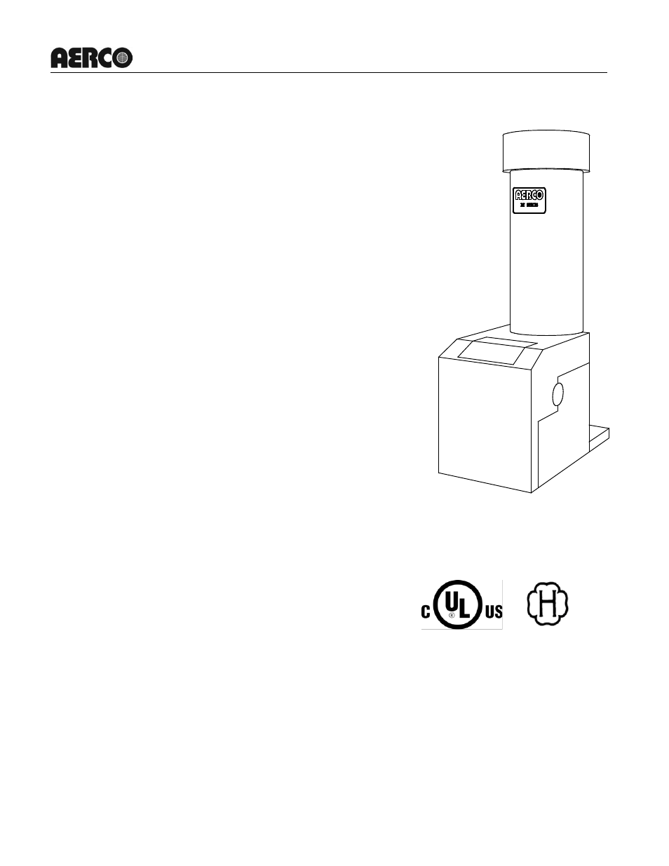
KC Series Low NOx Gas-Fired Water Heater
USER MANUAL
Applicable to Serial Numbers G-11-0694 and Above
KC Series
Low NOx
Gas Fired
Water Heating
System
Natural Gas or Propane Fired,
Condensing and Forced Draft Hot Water Heater
1,000,000 BTU/HR Input
Patent No. 4,852,524
Table of contents
Document Outline
- OMM-0029_0A_GF-111LN_KC HEATER-LN _G-11-0694 and UP_01_COVER_7-8-11
- OMM-0029_0A_GF-111LN_KC HEATER-LN _G-11-0694 and UP_02_TOC_3-28-11
- FOREWORD A
- Section 1 – SAFETY PRECAUTIONS 1-1
- Section 2 – INSTALLATION PROCEDURES 2-1
- Section 3 – CONTROL PANEL OPERATING PROCEDURES 3-1
- Section 4 – INITIAL START-UP 4-1
- Section 5 – SAFETY DEVICE TESTING PROCEDURES 5-1
- Section 6 – MAINTENANCE 6-1
- Section 7 – TROUBLESHOOTING 7-1
- Section 8 – RS232 COMMUNICATION 8-1
- APPENDICES
- OMM-0029_0A_GF-111LN_KC HEATER-LN _G-11-0694 and UP_03_CH1_7-8-11
- OMM-0029_0A_GF-111LN_KC HEATER-LN _G-11-0694 and UP_04_Ch2_4-19-11
- OMM-0029_0A_GF-111LN_KC HEATER-LN _G-11-0694 and UP_05_Ch3_4-19-11
- OMM-0029_0A_GF-111LN_KC HEATER-LN _G-11-0694 and UP_06_Ch4_6-21-10
- OMM-0029_0A_GF-111LN_KC HEATER-LN _G-11-0694 and UP_07_Ch5_3-24-11
- SECTION 5 - SAFETY DEVICE TESTING PROCEDURES
- 5.1 TESTING OF SAFETY DEVICES
- 5.2 LOW GAS PRESSURE FAULT TEST
- 5.3 HIGH GAS PRESSURE TEST
- 5.4 LOW WATER LEVEL FAULT TEST
- 5.5 WATER TEMPERATURE FAULT TEST
- 5.6 INTERLOCK TESTS
- 5.7 FLAME FAULT TEST
- 5.8 AIR FLOW FAULT TEST
- 5.9 SSOV PROOF OF CLOSURE SWITCH
- 5.10 PURGE SWITCH OPEN DURING PURGE
- 5.11 IGNITION SWITCH OPEN DURING IGNITION
- 5.12 SAFETY PRESSURE RELIEF VALVE TEST
- SECTION 5 - SAFETY DEVICE TESTING PROCEDURES
- OMM-0029_0A_GF-111LN_KC HEATER-LN _G-11-0694 and UP_08_Ch6_12-09-10
- 6.1 MAINTENANCE SCHEDULE
- 6.2 Spark Ignitor
- Figure 6.1
- Spark Ignitor and Flame Detector Location
- Figure 6.1
- 6.3 Flame Detector
- 6.4 COMBUSTION CALIBRATION
- 6.5 SAFETY DEVICE TESTING
- 6.6 BTU TRANSMITTER PUMP LUBRICATION
- Figure 6.2
- BTU Transmitter Pump Oil Port Locations
- 6.7 BTU TRANSMITTER ASSEMBLY
- Figure 6.3
- BTU Transmitter Pump Disassembly
- Figure 6.4
- Compression Fitting Locations
- Figure 6.5
- BTU Transmitter Disassembly
- Figure 6.6
- BTU Transmitter Pump Compression Fitting Locations
- Figure 6.7
- BTU Transmitter Hot Water Tube Disassembly
- Figure 6.8
- BTU Transmitter Shell Components
- Figure 6.9
- Impeller Housing Disassembly
- Figure 6.3
- 6.8 MANIFOLD AND EXHAUST TUBES
- Figure 6.10
- Grounding Terminal Location
- Figure 6.11
- Burner Disassembly Diagram
- Figure 6.12
- Exhaust Sensor Connector Location
- /
- Figure 6.13
- Blower Proof Switch Wire Location
- (older style switch shown at left, newer style at right)
- Figure 6.14
- Air/Fuel Valve Inlet Hose Clamp
- Figure 6.15
- Feedback Tube and Air/Fuel Valve to Differential Regulator Bolts
- Figure 6.16
- Manifold Nut and Bolt Locations
- 6.8.1 PROPANE UNITS
- Manifold Nut and Bolt Locations
- Figure 6.17
- Propane Air Regulator Measuring Taps
- Figure 6.10
- 6.9 HEAT EXCHANGER INSPECTION AND CLEANING
- 6.10 CONDENSATE DRAIN ASSEMBLY
- 6.11 LOW WATER CUTOFF PROBE INSPECTION AND CLEANING
- 6.12 HYDRAULIC ZERO NEEDLE VALVE ADJUSTMENT (C-More Control BOX)
- 6.13 FLAME STRENGTH MEASURMENT
- OMM-0029_0A_GF-111LN_KC HEATER-LN _G-11-0694 and UP_09_Ch7_3-28-11
- 7.1 INTRODUCTION
- 1. Inspect feed forward (BTU transmitter) sensor for loose or broken wiring.
- 2. Check resistance of sensor to determine if it is within specification.
- 1. Measure the actual exhaust temperature and continuity of the exhaust sensor. If the exhaust temperature is less than 500 o F and the exhaust sensor shows continuity replace the sensor.
- 2. If exhaust temperature is greater than 500 o F, check combustion calibration. Calibrate or repair as necessary.
- OMM-0029_0A_GF-111LN_KC HEATER-LN _G-11-0694 and UP_10_CH8_6-20-10-OLD
- OMM-0029_0A_GF-111LN_KC HEATER-LN _G-11-0694 and UP_11_App A_6-18-10
- OMM-0029_0A_GF-111LN_KC HEATER-LN _G-11-0694 and UP_12_App-B_10-01-09
- OMM-0029_0A_GF-111LN_KC HEATER-LN _G-11-0694 and UP_13_App C_05-06-09
- OMM-0029_0A_GF-111LN_KC HEATER-LN _G-11-0694 and UP_14_App D_3-24-11
- OMM-0029_0A_GF-111LN_KC HEATER-LN _G-11-0694 and UP_15_App-E_6-18-10
- OMM-0029_0A_GF-111LN_KC HEATER-LN _G-11-0694 and UP_16_App-F_05-06-09
- OMM-0029_0A_GF-111LN_KC HEATER-LN _G-11-0694 and UP_17_App G_05-06-09
- OMM-0029_0A_GF-111LN_KC HEATER-LN _G-11-0694 and UP_18_App H_12-27-08
- OMM-0029_0A_GF-111LN_KC HEATER-LN _G-11-0694 and UP_19_App I_05-06-09
- OMM-0029_0A_GF-111LN_KC HEATER-LN _G-11-0694 and UP_20_App J-SPARES
- OMM-0029_0A_GF-111LN_KC HEATER-LN _G-11-0694 and UP_21_warranty
- OMM-0029_0A_GF-111LN_KC HEATER-LN_G-11-0694 and UP_10_CH8_6-17-10
- Section 8 - RS232 COMMUNICATION
- INTRODUCTION
- RS232 COMMUNICATION SETUP
- MENU PROCESSING UTILIZING RS232 COMMUNICATION
- DATA LOGGING
- 8.4.1 Fault Log
- 8.4.2 Operation Time Log
- 8.4.3 Sensor Log
- Section 8 - RS232 COMMUNICATION
- Blank Page
- Blank Page
- Blank Page
- Blank Page
- Blank Page
- Blank Page
- Blank Page
- Blank Page
- Blank Page
- OMM-0029_0A_GF-111LN_KC HEATER-LN _G-11-0694 and UP_08_Ch6_2-14-12.pdf
- 6.1 MAINTENANCE SCHEDULE
- 6.2 Spark IgnitEr
- 6.3 Flame Detector
- 6.4 COMBUSTION CALIBRATION
- 6.5 SAFETY DEVICE TESTING
- 6.7 BTU TRANSMITTER ASSEMBLY
- 6.8 MANIFOLD AND EXHAUST TUBES
- 6.9 HEAT EXCHANGER INSPECTION AND CLEANING
- 6.10 CONDENSATE DRAIN ASSEMBLY
- 6.11 LOW WATER CUTOFF PROBE INSPECTION AND CLEANING
- 6.12 HYDRAULIC ZERO NEEDLE VALVE ADJUSTMENT (C-More Control BOX)
- 6.13 FLAME STRENGTH MEASURMENT