Installation, operation & mai, Ntenance – AERCO Modulex High Pressure Manual User Manual
Page 22
INSTALLATION, OPERATION & MAI
2-6
NTENANCE
FRONT VIEW – R.H.
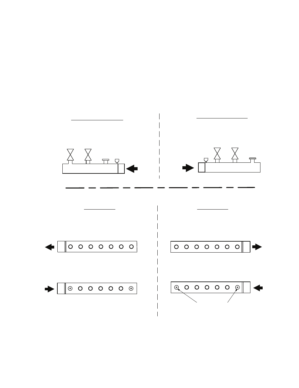
3. Disassemble the flow (supply) and return manifolds (Figure 2-5), leaving the rubber gaskets in place
on the upper holes of the aluminum sections and the rubber gaskets/diaphragms in place on the
lower holes. The diaphragms on the end sections have a hole diameter of .866 in. (22 mm).
4. Reassemble the manifolds with the threaded connection on the opposite side as shown in Figure
2-5. Change the position of the drain cock and the automatic air vent (Figure 2-6).
5. Reposition the temperature sensor white and red leads onto the new flow (supply) manifold and the
temperature sensor white and green leads onto the new return manifold.
GAS CONNECTIONS ON L.H. SIDE
(AFTER MODIFICATION CONDITION)
FRONT VIEW – L.H.
A
C
B
GAS CONNECTIONS ON R.H. SIDE
(STD. DELIVERY CONDITION)
A
C
B
REAR VIEW
REAR VIEW
C.H. FLOW AND RETURN
L.H. SIDE CONNECTIONS
(AFTER MODIFICATION CONDITION).
C.H. FLOW AND RETURN
R.H. SIDE CONNECTIONS
(STD DELIVERY CONDITION).
0.866" [22 mm]
0.866" (22 mm) = DIAPHRAGM FOR THE TWO
COLLECTORS POSITIONED AT THE EXTREME
ENDS
Figure 2-5
R.H. and L.H. Manifold Connection