Section 7 - maintenance, 1 maintenance schedule, 2 spark igniter – AERCO KC1000 Low NOx Boiler equipped with C-More 2003 User Manual
Page 51: Maintenance, Warning, Table 1 maintenance schedule
MAINTENANCE
7-1
SECTION 7 - MAINTENANCE
7.1 MAINTENANCE SCHEDULE
The unit requires regular routine maintenance to
keep up efficiency and reliability. For best
operation and life of the unit, the routine
maintenance procedures listed in Table 1 should
be performed within the specified time periods.
Table 1 Maintenance Schedule
Para
Item
6
Mos.
12
Mos.
24
Mos.
Labor
Time
7.2 Spark
Igniter
Inspect Replace
20
mins.
7.3 Flame
Detector
Inspect Replace
20
mins.
7.4 Combustion
Cal.
Check Check
1
hr.
7.5 Testing
of
Safety
Devices
Test
20
mins.
7.6 *Manifold
& Tubes
Inspect
& clean
if
needed
4 hrs.
7.7 Water
Side
Inspection
Inspect
2
hr.
7.8 Condensate
Drain
Inspect
& clean
30
mins.
* Recommended only when unit will be run in an
extreme condensing mode for prolonged periods
of time.
WARNING!
TO AVOID PERSONAL INJURY, BEFORE
SERVICING:
(A) DISCONNECT AC POWER FROM THE
UNIT.
(B) SHUT OFF THE GAS SUPPLY TO THE
UNIT.
(C) ALLOW THE UNIT TO COOL TO A SAFE
TEMPERATURE.
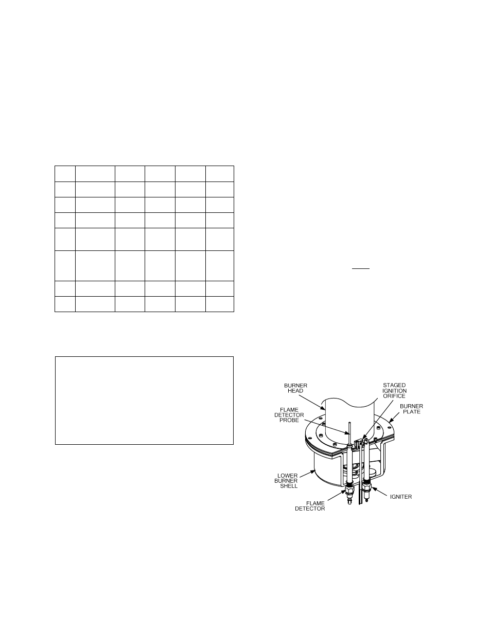
7.2 SPARK IGNITER
The spark igniter assembly is located in the body
of the burner (Figure 7.1). The igniter may be
HOT. Care should be exercised. It is easier to
remove the igniter from the unit after the unit has
cooled to room temperature.
To inspect or replace the Igniter :
1. Set
the
ON/OFF switch on the control panel
to the OFF position and disconnect AC
power from the unit.
2. To access the spark igniter, remove the
unit’s left side paneland left rear cover.
3. Disconnect the igniter cable from the igniter
contact.
4. Using a 15/16” open-end wrench, remove
the igniter from the burner shell.
5. Inspect the igniter for erosion or carbon
build-up. If there is substantial erosion of the
spark gap or ground electrode, the igniter
should be replaced. If carbon build-up is
present, clean the igniter using fine emery
cloth. Repeated carbon build-up on the
igniter is an indication that a check of the
combustion settings is required. See Section
4 for Combustion Calibration procedures.
6. Prior to reinstalling the igniter, a conductive
anti-seize compound must be applied to the
igniter threads.
7. Reinstall the igniter in the burner shell. Do
Not over-tighten. A slight snugging up is
sufficient.
8. Reconnect the igniter cable.
9. Replace the left side panel and left rear
cover on the unit.
Figure 7.1
Spark Igniter and Flame Detector Location